Powermax – Hypertherm Powermax105 Service Manual User Manual
Page 277
Power SuPPly ComPonent rePlaCement
powermax
105 Service Manual
9-79
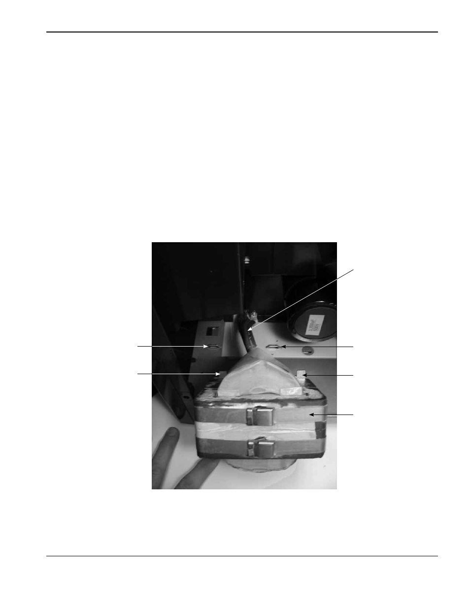
3. Lift the PFC inductor out of the power supply, while carefully guiding the PFC inductor wires through the opening in
the bottom of the center panel.
Note: 230-400 V CE and 380 V CCC/230-400 V CE models have a ferrite core installed over the longer
PFC inductor wires, on the power board side, that must be removed while removing the PFC inductor
from the power supply.
4. Place the new PFC inductor in the power supply, while guiding the PFC inductor wires through the opening in the
bottom of the center panel.
5. Slide the tabs on the front of the PFC inductor into the slots in the base of the power supply.
6. Tighten the two supplied mounting screws in the base of the PFC inductor to 69.1 kg cm (60 in.-lbs).
7. If the power supply is a 230-400 V CE or 380 V CCC/230-400 V CE model, install the ferrite core over the longer
PFC inductor wires on the power board side of the power supply.
8. Secure the PFC inductor wires to the power board using the screw and bolt removed in an earlier step, while
referring to the applicable figure on the previous two pages. Tighten the screw to 40.3 kg cm (35 in.-lbs) and the
bolt at J25 to 63.4 kg cm (55 in.-lbs).
PFC Inductor
PFC Inductor wires (4)
Slot in base
Slot in base
PFC Inductor tab
PFC Inductor tab