Powermax, Power supply component replacement 9-76, 105 service manual – Hypertherm Powermax105 Service Manual User Manual
Page 274
Power SuPPly ComPonent rePlaCement
9-76
powermax
105 Service Manual
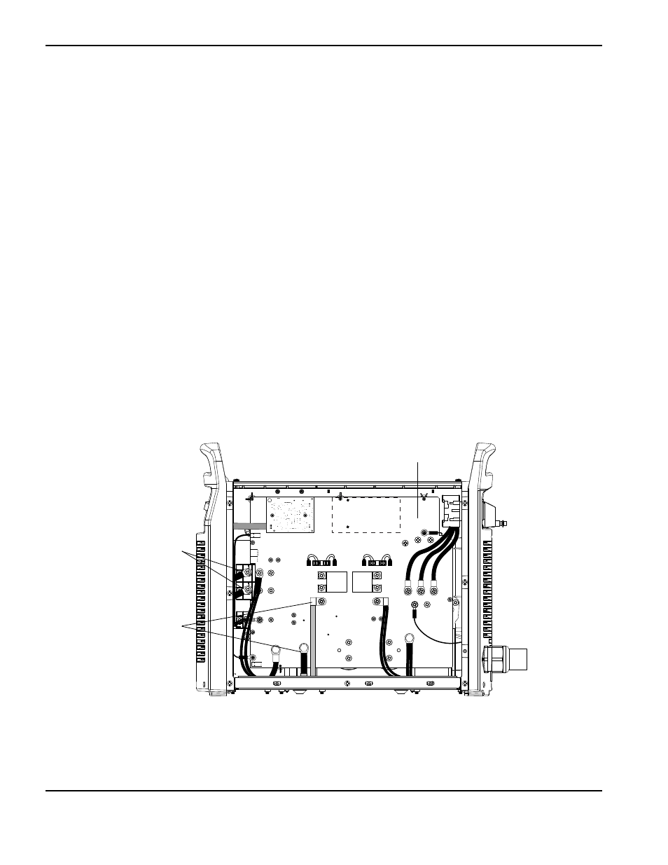
7. Place the new transformer in the power supply, while guiding the transformer wires through the opening in the
bottom of the center panel.
8. Slide the tabs on the front of the transformer into the slots in the base of the power supply.
9. Tighten the two supplied mounting screws in the base of the transformer to 69.1 kg cm (60 in.-lbs).
10. Align the two bottom fan holes with the corresponding holes in the center panel.
11. Tighten the two fan mounting screws to 23 kg cm (20 in.-lbs).
12. If the power supply is a CE or CCC model, install the two ferrite cores over the long transformer wires, on the
power board side.
13. Secure the long transformer wires to the output diode bridge by tightening the screws to 40.3 kg cm (35 in.-lbs).
14. Secure the short transformer wires to the power board using the screw and bolt removed in an earlier step. Tighten
the screw to 40.3 kg cm (35 in.-lbs) and the bolt at J26 to 63.4 kg cm (55 in.-lbs).
J22
J21
J20
J19
J27
WORK
LEAD
J26
J25
+
_
+
_
RED
J18
ORG
J17
J32
J11
B
R
J28
TP7
TP9
TP8
W
R
B
Long transformer
wires
Short transformer
wires
Power board