Powermax – Hypertherm Powermax105 Service Manual User Manual
Page 236
Power SuPPly ComPonent rePlaCement
9-38
powermax
105 Service Manual
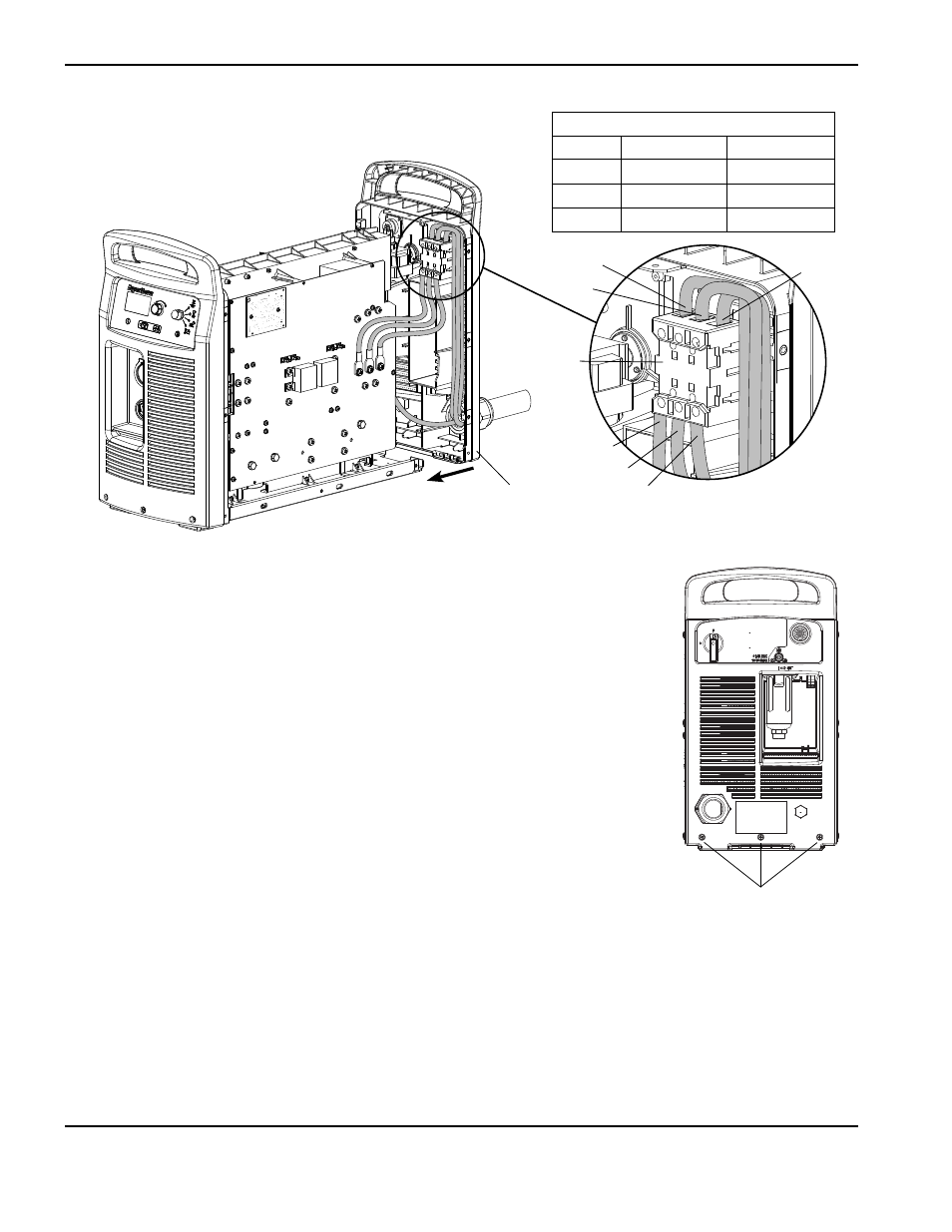
18. Insert the red and black wires in the top of the auxiliary switch and tighten the set
screws to 11.5 kg cm (10 in.-lbs). The red wire connects to the "13" terminal and the
black wire connects to the "14" terminal.
19. Insert the three power wires in the bottom of the power switch, in the same order as
they were removed, and tighten the T1-T2-T3 set screws to 23 kg cm (20 in.-lbs).
20. Insert the three power wires in the top of the power switch, in the same order as they
were removed, and tighten the L1-L2-L3 set screws to 23 kg cm (20 in.-lbs).
21. Slide the rear end panel against the power supply chassis.
22. Tighten the three mounting screws in the bottom of the rear end panel to
23 kg cm (20 in.-lbs).
Rear end panel
mounting screws
Rear end panel
T1
L2
Power
switch
L3
L1
T2
T3
Power cord connections
Wire
CSA
CE or CCC
L1
Black
Brown
L2
White
Black
L3
Red
Gray