Configuration dependent prime 1 through 8 menu, 3 configuration dependent prime 1 through 8 menu – Comtech EF Data SMS-7000 User Manual
Page 85
SMS-7000 Modem Protection Switch
Operation
Rev. 3
3–15
3.4.3
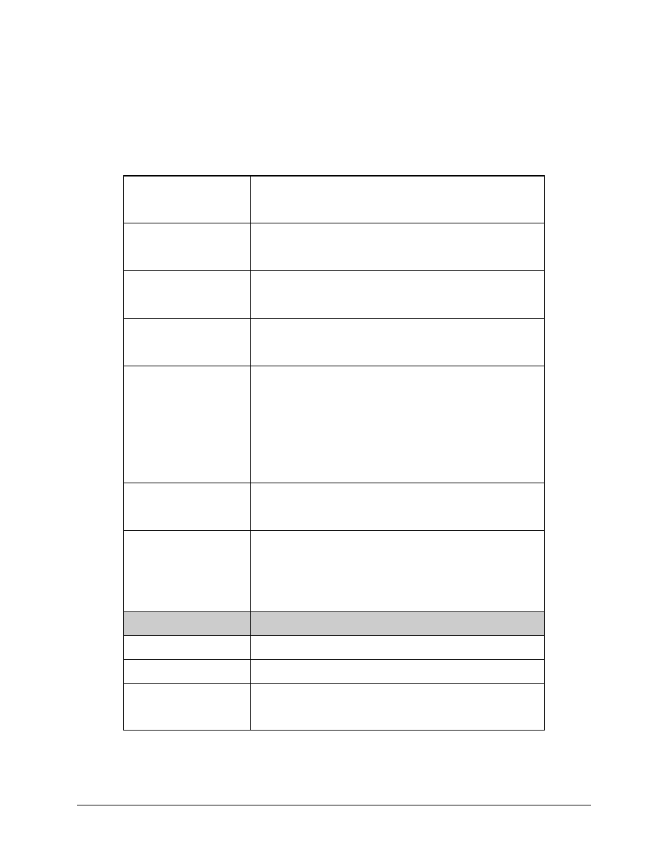
Configuration Dependent Prime 1 through 8 Menu
PRIME MODEM #n
ADDRESS
Set # other than 0. Address 0 is a global address.
Upon entry, the current status is displayed. Press [
↑] or [ ↓] to make
the selection. Press [ENTER] to execute the change.
PRIME MOD #n
Must be On for the switch to recognize as active.
Upon entry, the current status is displayed. Press [
↑] or [ ↓] to make
the selection. Press [ENTER] to execute the change.
PRIME DEMOD #n
Must be On for the switch to recognize as active.
Upon entry, the current status is displayed. Press [
↑] or [ ↓] to make
the selection. Press [ENTER] to execute the change.
PRIME MODEM #n
PRIORITY
Options: LOW, MEDIUM, and HIGH.
Upon entry, the current status is displayed. Press [
↑] or [ ↓] to make
the selection. Press [ENTER] to execute the change.
PRIME MODEM #n
DELAY
AUTO = 2 times sweep period
MANUAL = 0.5 to 127.0 SEC.
To switch properly in DEPENDENT mode, the Prime modem demods
must have input from a source modem other than their own. Otherwise,
when the delay is set to NONE, the switch will oscillate between prime
and backup modems. This occurs because the output of the modulator
has been interrupted while the whole modem attempts to switch.
Upon entry, the current status is displayed. Press [
↑] or [ ↓] to make
the selection. Press [ENTER] to execute the change.
PRIME #n MULTIPLEXER
Displayed if multiplexer is; ‘YES or NO.’
Upon entry, the current status is displayed. Press [
↑] or [ ↓] to make
the selection. Press [ENTER] to execute the change.
PRIME DEMOD #n
MULTIPLEXER
ADDRESS
(Menu applies, only if
multiplexer is attached.)
Set # other than 0. Address 0 removes the multiplexer from the system.
Address: 0 to 255
Upon entry, the current status is displayed. Press [
↑] or [ ↓] to make
the selection. Press [ENTER] to execute the change.
BREAKOUT #n
CONFIGURATION
Press [ENTER] to access submenus.
D & I
Use the BNC connectors for Unbalanced.
Use the DB15 connector for Balanced.
EXTERNAL CLOCK
Use the BNC connectors for Unbalanced.
Use the DB15 connector for Balanced.
INSERT DATA INPUT
Options: NORMAL/LOOP
Select LOOP if insert clock is selected as receive buffer clock source at
the modem. This connects DDO to IDI. (Drop Data Out to Insert Data
In).