Comtech EF Data SMS-7000 User Manual
Page 116
Maintenance
SMS-7000 Modem Protection Switch
5–4
Rev. 3
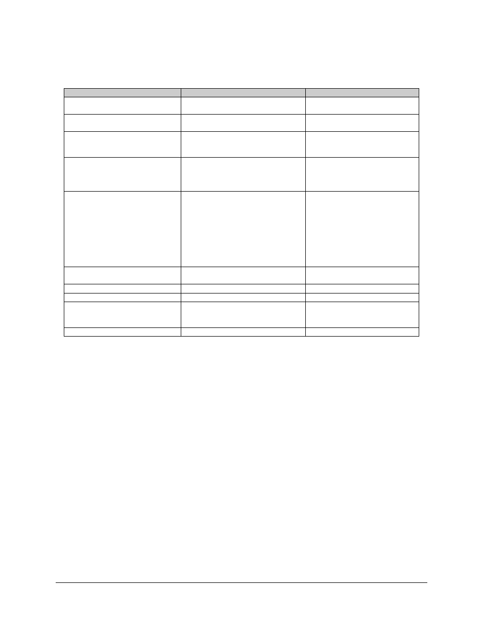
Table 5-1. Switch Fault Analysis (Continued)
Fault
Description
Action
NO MOD CONFIG LOADED
No configuration for modulators in
memory.
Reload modem configuration from
Load/Verify menu.
NO DMOD CONFIG LOADED
No configuration for modulators in
memory.
Reload modem configuration from
Load/Verify menu.
NO PRIMES ASSIGNED
Backup only.
Backup is enabled for switching with no
prime assignments.
Disable backup in configuration
menu to OFF if not in use.
Designate prime assignments.
PRIME NOT ASSIGNED
Prime only.
Prime is enabled in switching algorithm
but has not been assigned a backup.
Disable prime in configuration menu
to OFF if not in use.
Designate backup assignment for
prime.
DATA SWITCH MODULE #1 to 8
or IF SWITCH MODULE
Set if module does not respond to
commands from the SCU, or responds
with error message.
If error is for single module, replace
module. It is recommended that
power be removed from the switch
when changing a data switch
module.
If error is indicated by multiple
modules, check data switch interface
cable (J4) on rear of SCU and
control unit.
POWER SUPPLY #1 FAULT
POWER SUPPLY #2 FAULT
Set when power supply voltage(s) are
out of tolerance.
Replace faulted power supply
module.
M&C CONTROLLER FAULT
Replace controller.
I2C BUS FAULT
Replace controller.
MU COMM FAILURE
Multiplexer fails to respond to switch
commands on the modem remote bus,
J2 of the SCU.
Same as MODEM COMM
FAILURE.
NO ADDRESS FOR MU
Address in configuration menu set to 0.
Enter correct multiplexer address.