Figure 1-2. block diagram – Comtech EF Data SMS-7000 User Manual
Page 27
SMS-7000 Modem Protection Switch
Introduction
Rev. 3
1–7
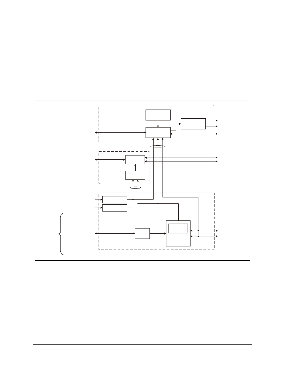
The switch functional block diagram (Figure 1-2) displays the functional partitioning and
interconnection between the three chassis.
Two cables interconnect the three units. The SCU and DSU are connected via a cable
that transfers power, faults, and switch control between the two chassis. Power, modem
faults, and switch faults originate from the DSU, while switch control commands are
initiated by the SCU. The IFU is connected to the DSU in the same manner.
D ATA S W ITC H
M :N x8
S LAV E
C O N TR O L LE R
L O W V O LTA G E
P O W E R
LO W V O LTA G E
P O W E R
B O P
x8
P R IM E P O W E R IN
P R IM E P O W E R IN
x2 D B 5 0
B A C K U P M O D E M D ATA
R X /T X
x8 D B 5 0
P R IM A R Y M O D E M D ATA
R X /T X
F R O N T PA N E L
FA U LT A N D
S TATU S R E LAY S
C O N T R O LL E R
R E M O T E C O N T R O L
E IA -4 85 /2 32
D B 9
S W IT C H FA U LTS
x2 D B 2 5
O N L IN E S TATU S
D B 9 E IA -4 8 5
M O D E M R E M O T E
C O N T R O L U N IT
D ATA S W ITC H U N IT
FA U LTS
E IA -4 85
IB S /ID R
B A LA N C E D D ATA
E IA -4 22
G .703
V.3 5
E IA -2 32 -C
D B 2 5
D B 1 5
D B 2 5
D B 2 5
U N B A LA N C E D DATA 5 C O A X
D & I
G .7 0 3
E X T E R N A L C L O C K
A U X IL IA R Y D ATA
A D P C M
E S C
A LA R M S
D B 9
D B 25
D B 25
T E R R E S T R IA L
D ATA , x 8
S L AV E
C O N T R O L LE R
C O A X
S W IT C H
IF S W IT C H U N IT
1 6 C O A X
P R IM A RY M O D E M IF
R X /T X
4 C O A X
B A C K U P M O D E M IF
R X /T X
U P /D O W N LIN K
1 6 C O A X
C A /07 5 5
C A /53 6 1
Figure 1-2. Block Diagram