Monitors, 4 monitors – Comtech EF Data SMS-7000 User Manual
Page 108
Theory of Operation
SMS-7000 Modem Protection Switch
4–4
Rev. 3
4.1.4 Monitors
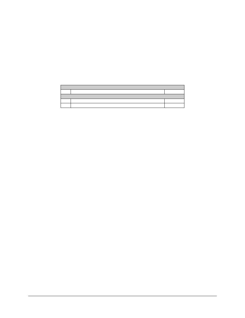
Three connectors provide switch status and fault information on the rear of the SCU
chassis (refer to Table 4-2).
Table 4-2. SCU Chassis Connectors
Switch Faults
J3
System, Equipment, and Stored Faults
9-pin D
Online Status
J6
Indicates whether prime modulators are on or offline
25-pin D
J5
Indicates whether prime demodulators are on or offline
25-pin D
Each set of fault output pins is isolated from internal switch electronics through single-
pole and double-throw relays. The three contacts of each relay are provided to the user
for direct application of visual and audio indicators. Relay contacts will support 1 mA of
continuous current at up to 30 VDC.
Normally open (NO) pins are connected to common (COM) for non-faulted indications
and online conditions. There is, however, one exception: the switch “COMMON
EQUIPMENT” fault has the normally closed (NC) contact connected to the common
(COM) for a no-fault condition (relay normally energized). This ensures that a fault is
indicated in the event of switch power loss.