Protection switch, Description, 4 protection switch – Comtech EF Data SMS-7000 User Manual
Page 26: 2 description
Introduction
SMS-7000 Modem Protection Switch
1–6
Rev. 3
1.1.4 Protection
Switch
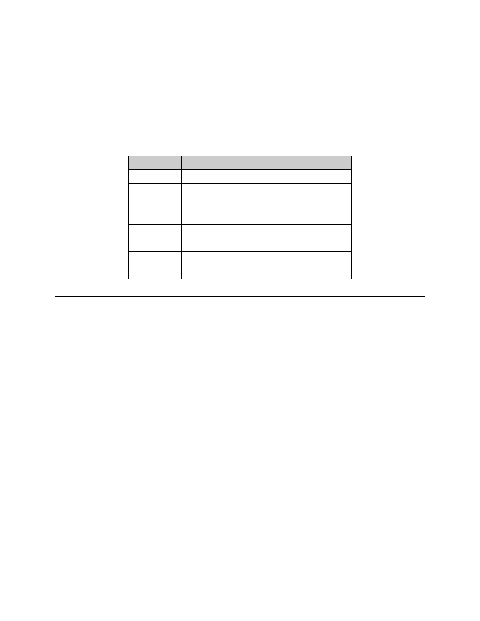
Refer to Table 1-4 for part numbers of various switch component.
Table 1-4. Protection Switch
Part Number
Description
PL/4800
Chassis Controller
PL/4801-1
IF Switch, 75
Ω
PL/4801-2
IF Switch, 50
Ω
PL/4802
Switch, Data
PL/4803
Power Supply, AC
PL/4831
Power Supply, DC
CA/5343
Cable Assembly, 15-Pin, EMI
CA/5361-1
Cable Assembly, Switch to Controller, 6 ft. (182.88 cm)
1.2 Description
The switch (Figure 1-1) is composed of three units:
•
Switch Control Unit (SCU) — User interface for switch and modem control
and configuration.
•
Data Switch Unit (DSU) — As commanded by the SCU, performs terrestrial
data configuration and backup modem data switching.
•
IF Switch (IFU) — As commanded by the SCU, performs backup modem IF
switching.
This 3-chassis arrangement gives the user control of the switch from the one unit (1U)
rack mounted SCU front panel. The DSU and IFU, which contain all terrestrial and link
interfaces, are mounted inside the rack to minimize rack and external interface cabling.
These units will accommodate the particulars of external interface requirements. They
can be separated or joined together and mounted either in the rear or on the top of the
rack.