Led indicators, 1 led indicators – Comtech EF Data SMS-7000 User Manual
Page 73
SMS-7000 Modem Protection Switch
Operation
Rev. 3
3–3
3.2.1 LED
Indicators
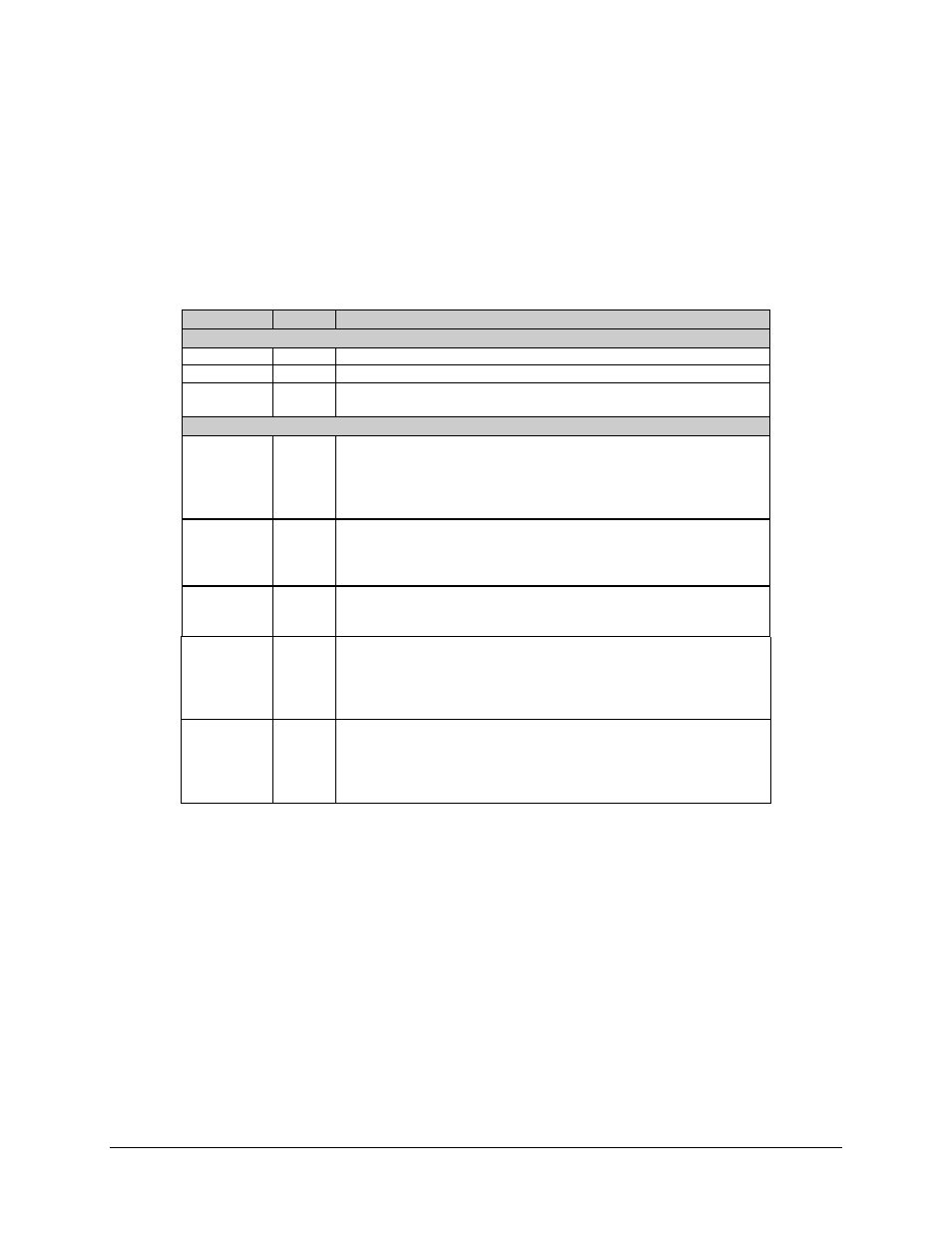
The eight LEDs on the front panel indicate the following (see Table 3-1):
Table 3-1. LED Indicators
Name
LED
Description
Status
Power On
Green
Indicates that power is applied to the switch.
Auto
Green
Indicates the switch is automatically assigning backup modems.
Manual
Green
Indicates the backup modems are being assigned as directed by the user
from the manual menu.
Switch Fault
System
Red
Indicates a communications failure or a configuration anomaly between
the switch and the attached modems. Specifics are displayed in the
Fault/Alarm menu. For example, mixing modems (without paying
attention to Table 1-1) in a rack will cause this fault, due to differences in
the remote communications commands.
Equipment
Red
Indicates a communications failure between the switch modules or a
detected fault within the switch hardware. Specifics are displayed in the
Fault/Alarm menu. For example, a power supply not plugged in will
indicate this fault.
Stored
Yellow
Indicates that a fault occurrence has been logged and stored. Specifics are
displayed in the Stored Fault/Alarms menu.
The fault may or may not be active.
Transmit
Yellow
Indicates a faulted prime modulator which has not been backed up. The
identity of the faulted modem(s) is displayed in the switch Fault/Alarm
menu. Specifics are displayed in the Fault/Alarm menu of the individual
modems. This fault clears when the faulted prime is backed up or when
the fault is removed.
Receive
Yellow
Indicates a faulted prime demodulator which has not been backed up. The
identity of the faulted modem(s) is displayed in the switch Fault/Alarm
menu. Specifics are displayed in the Fault/Alarm menu of the individual
modems. This fault clears when the faulted prime is backed up, or when
the fault is removed.