Comtech EF Data SMS-7000 User Manual
Page 140
M-2000-Multiplexer Utilization
SMS-7000 Modem Protection Switch
B–2
Rev. 3
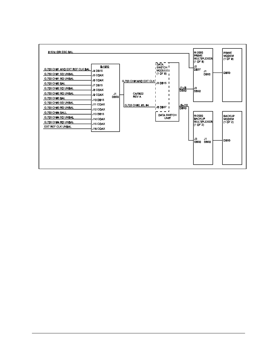
Figure B-1. Terrestrial Data Interconnections
Refer to Table B-1 for signal pinout information on the data switch module J6 connector
equipped with a MUX.
Note: The 8 kbit/s IDR overhead data channel can be directly connected to the prime
multiplexer. The 8 kbit/s overhead will not be switched to the backup in the event of a
prime modem and/or multiplexer failure.
Connect all multiplexers via Remote port (J5) to Modem Remote (J2) on the switch
M&C with an EIA-485 2-wire cable. All multiplexers must be configured for EIA-485
(2-wire), 9600 or 19200 baud with a unique address. Refer to the M-2000 Multiplexer
Installation and Operation Manual for further information on the MUX.
See also other documents in the category Comtech EF Data Equipment:
- CDD-880 (124 pages)
- CDM-800 (130 pages)
- ODMR-840 (184 pages)
- CDM-750 (302 pages)
- CDM-840 (244 pages)
- SLM-5650A (420 pages)
- CTOG-250 (236 pages)
- CDM-700 (256 pages)
- CDM-760 (416 pages)
- CDM-710G (246 pages)
- CDM-600/600L (278 pages)
- CDMR-570L (512 pages)
- CDM-625 (684 pages)
- CDM-625A (756 pages)
- CDD-564A (240 pages)
- CDD-564L (254 pages)
- CLO-10 (134 pages)
- MCED-100 (96 pages)
- CDMR-570AL (618 pages)
- CDM-600 LDPC (2 pages)
- BUC Power Supply Ground Cable (2 pages)
- MPP70 Hardware Kit for CDM-570L (4 pages)
- MPP50 Hardware Kit for CDM-570L (4 pages)
- CDM-625 DC-AC Conversion (4 pages)
- CDM-625 DC-AC Conversion with IP Packet Processor (4 pages)
- DMDVR20 LBST Rev 1.1 (117 pages)
- DMD2050E (212 pages)
- DMD-2050 (342 pages)
- DMD1050 (188 pages)
- OM20 (220 pages)
- QAM256 (87 pages)
- DD240XR Rev Е (121 pages)
- MM200 ASI Field (5 pages)
- DM240-DVB (196 pages)
- MM200 (192 pages)
- CRS-150 (78 pages)
- CRS-280L (64 pages)
- CRS-170A (172 pages)
- CRS-180 (136 pages)
- SMS-301 (124 pages)
- CiM-25/8000 (186 pages)
- CiM-25 (26 pages)
- CRS-500 (218 pages)
- CRS-311 (196 pages)
- CIC-20 LVDS to HSSI (26 pages)