Switch controller unit (scu), 1 switch controller unit (scu) – Comtech EF Data SMS-7000 User Manual
Page 28
Introduction
SMS-7000 Modem Protection Switch
1–8
Rev. 3
1.2.1
Switch Controller Unit (SCU)
The SCU is a one unit (1U), 19-inch (48.26 cm) rack-mounted chassis that provides the
configuration and automatic switching control functions. Rear panel connectors on this
chassis provide all user remote control and status interfaces and rack internal control
interfaces. The front panel provides local control of the switch.
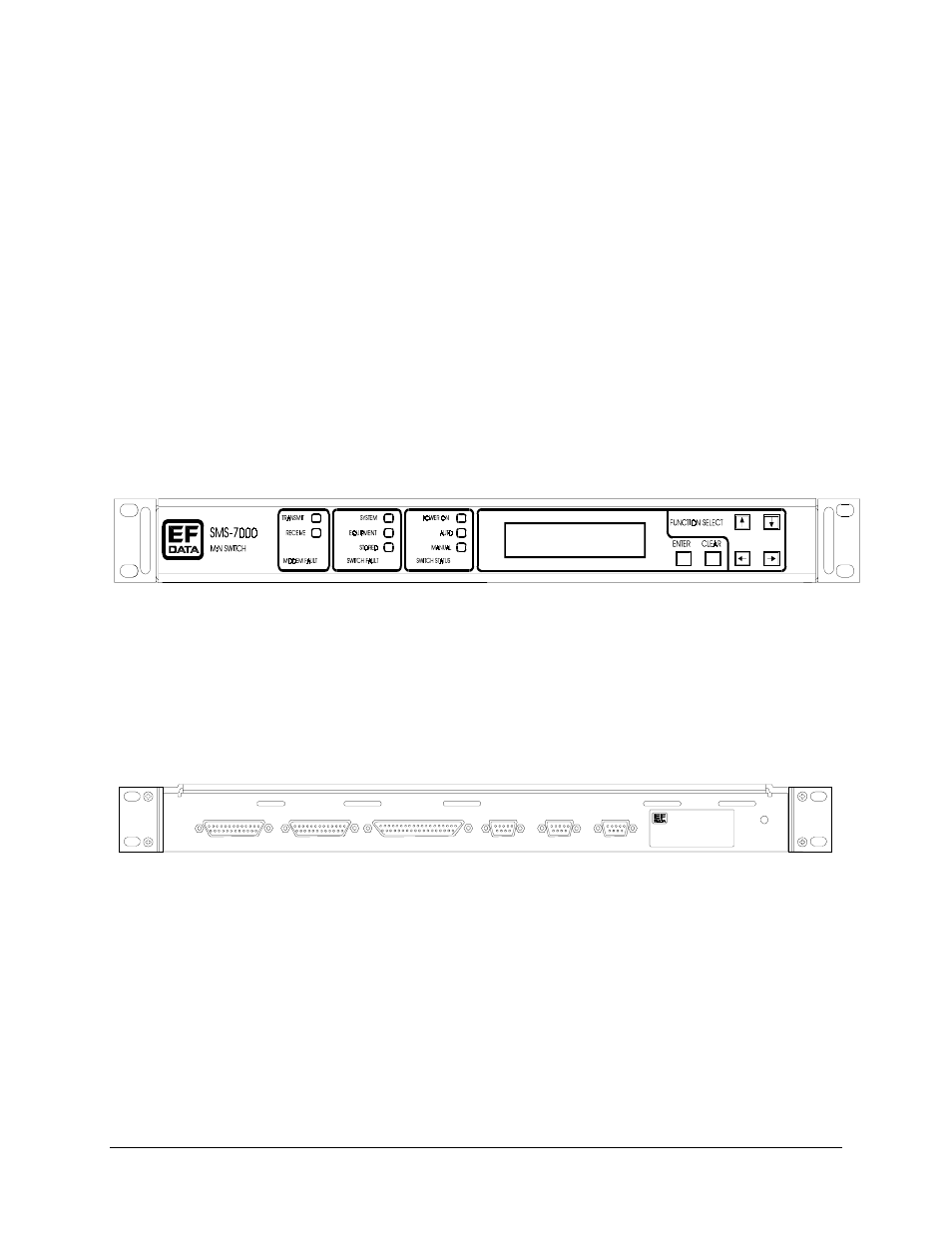
The SCU front panel (Figure 1-3) provides the user with visual fault and status
indicators. The back-lit display and keypad provide the local user control interface. The
front panel is a typical Comtech EFData modem front panel status and control interface.
The switch front panel supports all functions of the remote port. The user may configure
both the switch and associated modems as well as query status and faults.
Note: The modem control feature is only available with certain modems. Refer to the
compatibility chart (Table 1-3) for specific applications.
Figure 1-3. SCU Front Panel
The SCU rear panel (Figure 1-4) accommodates the user serial command interface for
remote configuration and status. These interfaces are also shown in the block diagram
(Figure 1-2).
J 6
J 6
J 3
J 2
J 1
J 4
PR IME M OD
STATUS
PR IME M OD
STATUS
SW IT CH
FAULTS
MO DE M
RE MO TE
US ER
RE MO TE
DATA SW IT CH
INT ER FA CE
Figure 1-4. SCU Rear Panel
Prime modulator and demodulator status and switch faults are provided on dedicated I/O
connectors. Status and fault conditions are indicated at these connectors by opening and
closing relay contacts, which may be used to directly trigger external alarms and
indicators. The modem remote port is the control interface to all modems attached to the
switch. The Data Switch Interface, which carries control and fault information between
the switch chassis and SCU, is also provided.