2 modem remote (j2), 3 switch faults (j3) – Comtech EF Data SMS-7000 User Manual
Page 57
SMS-7000 Modem Protection Switch
Installation
Rev. 3
2–23
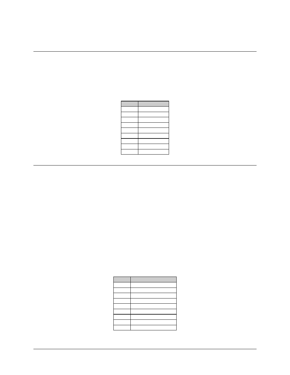
2.6.1.2
Modem Remote (J2)
The modem remote interface is a 2-wire EIA-485, 9600, or 19200 baud. The connector is
a 9-pin female D, with the pinouts as shown in Table 2-5.
Table 2-5. Modem Remote EIA-485 Connector (J2)
Pin #
Signal Name
1
GND
2
Unused
3
Unused
4
+RX/TX
5
-RX/TX
6
Unused
7
Unused
8
+RX/TX
9
-RX/TX
2.6.1.3
Switch Faults (J3)
Switch fault outputs on this connector are provided by Form C relay contacts for status
monitoring.
• Controller Fault is indicated by a Common-to-Normally Closed contact closure,
activated if the controller loses power.
• M:N faults are indicated by a Common-to-Normally Open contact closure,
activated in the event of any fault registered in the Fault Alarm Menus.
Maximum relay contact current is 1A at 30 VDC.
The connector is a 9-pin female D with the pinouts as shown in Table 2-6.
Table 2-6. Switch Faults Connector (J3)
Pin #
Signal Name
1
Controller Fault NO
2
Controller Fault COM
3
Controller Fault NC
4
M:N Fault NO
5
M:N Fault COM
6
M:N Fault NC
7
Spare 2 NO
8
Spare 2 COM
9
Spare 2 NC