Comtech EF Data SMS-7000 User Manual
Page 63
SMS-7000 Modem Protection Switch
Installation
Rev. 3
2–29
2.6.2.2
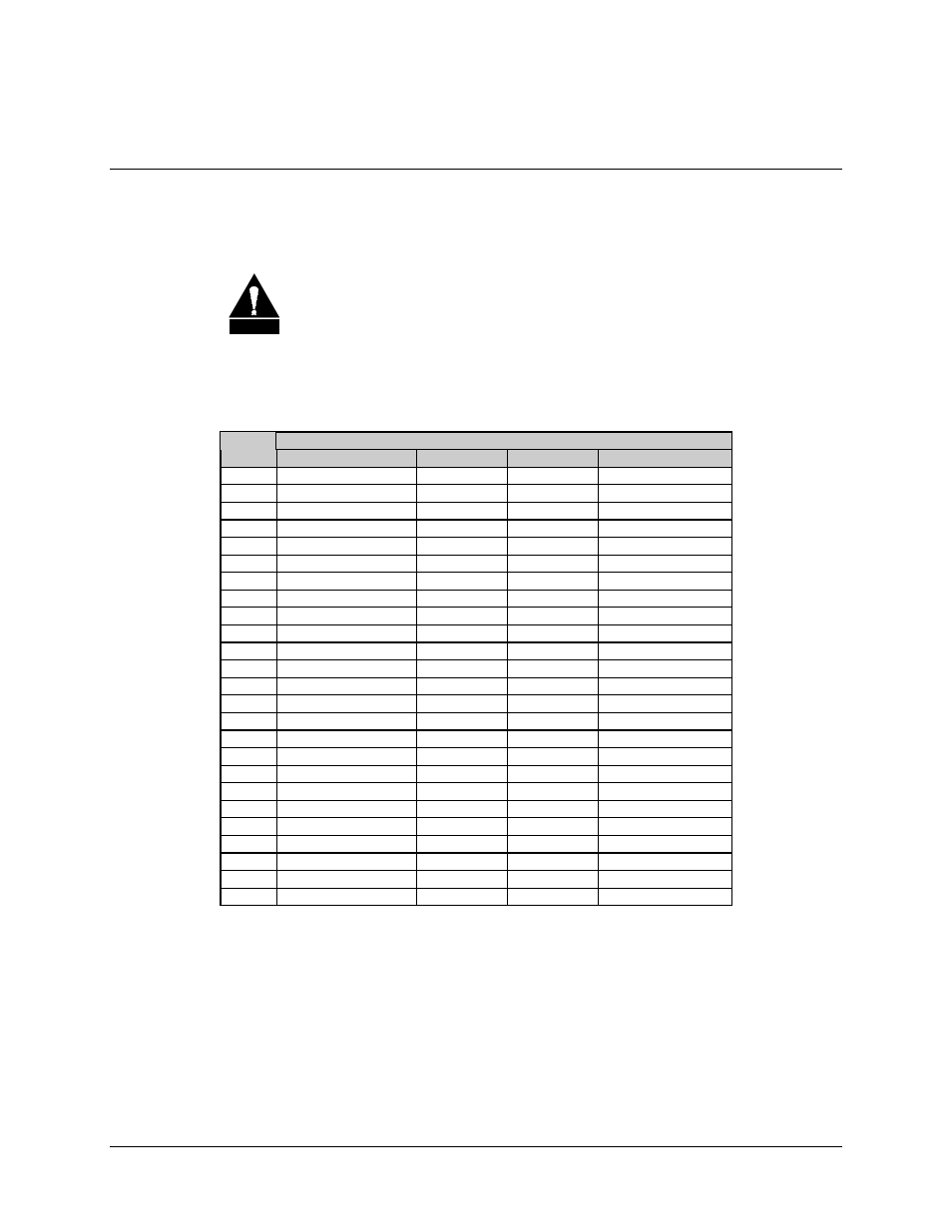
V.35/EIA-232-C Terrestrial Data (J1)
The V.35 terrestrial data connector (one of three IBS data options) is a 25-pin female D,
with one connector per channel (refer to Table 2-10).
C AU TIO N
When using this port, be certain there is no connection to the J6 (EIA-422)
or J3 (G.703) ports. When using EIA-232 data, all data switch modules
must have jumper JP1 in EIA-232 position (with jumpers connecting the
middle pin and the pin furthest from the front of the switch module). For
V.35, all jumpers must be in EIA-422 position.
Table 2-10. V.35/EIA-232 Terrestrial Data Connectors (J1)
Signal Name
Pin #
IBS V.35
IDR
D&I
EIA-232-C
1
SHIELD
SHIELD
2
SD A
SD
3
RD A
RD
4
RTS
C
C
RTS
5
CTS
A
A
CTS
6
DSR
B
B
DM
7
SIG GND
L
L
SIG GND
8
RLSD
E
E
RR
9
SCR B
EXT CLK
10
11
SCTE B
12
SCT B
R
R
13
E
E
14
SD B
M
M
15
SCT A
O
O
ST
16
RD B
V
V
17
SCR A
E
E
RT
18
D
D
19
20
EXC A
21
22
23
EXC B
24
SCTE A
(TT)
25
A
Note: For all eight switch modules, JP1 must be either set all EIA-232 or all
EIA-422/V.35/G.703 (JP1 set in the EIA-422/V.35/G.703 position works for most
applications).