Message structure, A.2 message structure – Comtech EF Data SMS-7000 User Manual
Page 119
SMS-7000 Modem Protection Switch
Remote Control Operation
Rev. 3 Draft
A–3
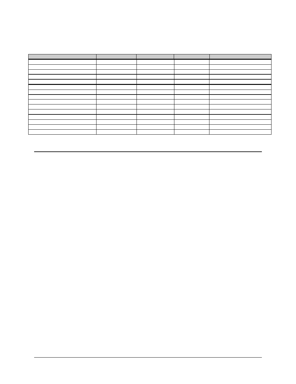
Table A-1. SMS-7000 Remote Control: SMS-658/SMS-758 Comparison Table (Continued)
Command
SMS-7000
SMS-658
SMS-758
Notes
TX Operational Stored Faults
TOSF_#
SMS-7000 only
RX Operational Stored Faults
ROSF_#
SMS-7000 only
Backup Modem System Stored Faults
SSF_Bn_#
SMS-7000 only
Prime Modem System Stored Faults
SSF_n_#
SMS-7000 only
Equipment Stored Faults
ESF_#
SMS-7000 only
Bulk Consolidated Status Faults
BCSF_
BCSF_
BCSF_
Different response
Equipment Type
ET_
ET_
ET_
Different response
M&C Firmware Information
MCFI_
SMS-7000 only
Data Switch Module Firmware Info
DMFI_
SMS-7000 only
IF Switch Module Firmware Info
IMFI_
SMS-7000 only
Firmware Version Status
VER_
VER_
SMS-658/SMS-758 only
Backup Multiplexer Attached
MU_Bx_yyy
SMS-7000 only
Backup Multiplexer Address
MUA_Bx_yyy
MUA_Bx_yyy
MUA_Bx_yyy
Prime Multiplexer Attached
MU_x_yyy
SMS-7000 only
Prime Multiplexer Unit Address
MUA_x_yyy
MUA_x_yyy
MUA_x_yyy
A.2 Message
Structure
The ASCII character format used requires 11 bits/character:
• 1 start bit
• 7 information bits
• 1 parity bit
• 2 stop bits
or
• 1 start bit
• 8 information bits
• no parity bit
• 2 stop bits
Messages on the remote link fall into the categories of commands and responses:
• Commands are messages which are transmitted to a switch
• Responses are messages returned by a switch in response to a command
The general message structure is as follows:
• Start Character
• Device Address
• Command/Response
• End of Message Character