3 dsu (j12) to ifu (j1), 4 dsu j9 (bu1) modem connector to backup modem, 5 dsu ji ch to prime modem – Comtech EF Data SMS-7000 User Manual
Page 50
Installation
SMS-7000 Modem Protection Switch
2–16
Rev. 3
2.4.1.3
DSU (J12) to IFU (J1)
Refer to Figure 2-5.
Cable Assembly Part No. CA/5343 is provided with the switch. This is a single cable
interface between the two switching sections, J12 IF Control Interface on the DSU and
J1 IF Control Interface on the IFU. The cable carries EIA-485 at 9600 baud, control
signals, and power.
2.4.1.4
DSU J9 (BU1) Modem Connector to Backup Modem
Refer to Figure 2-5.
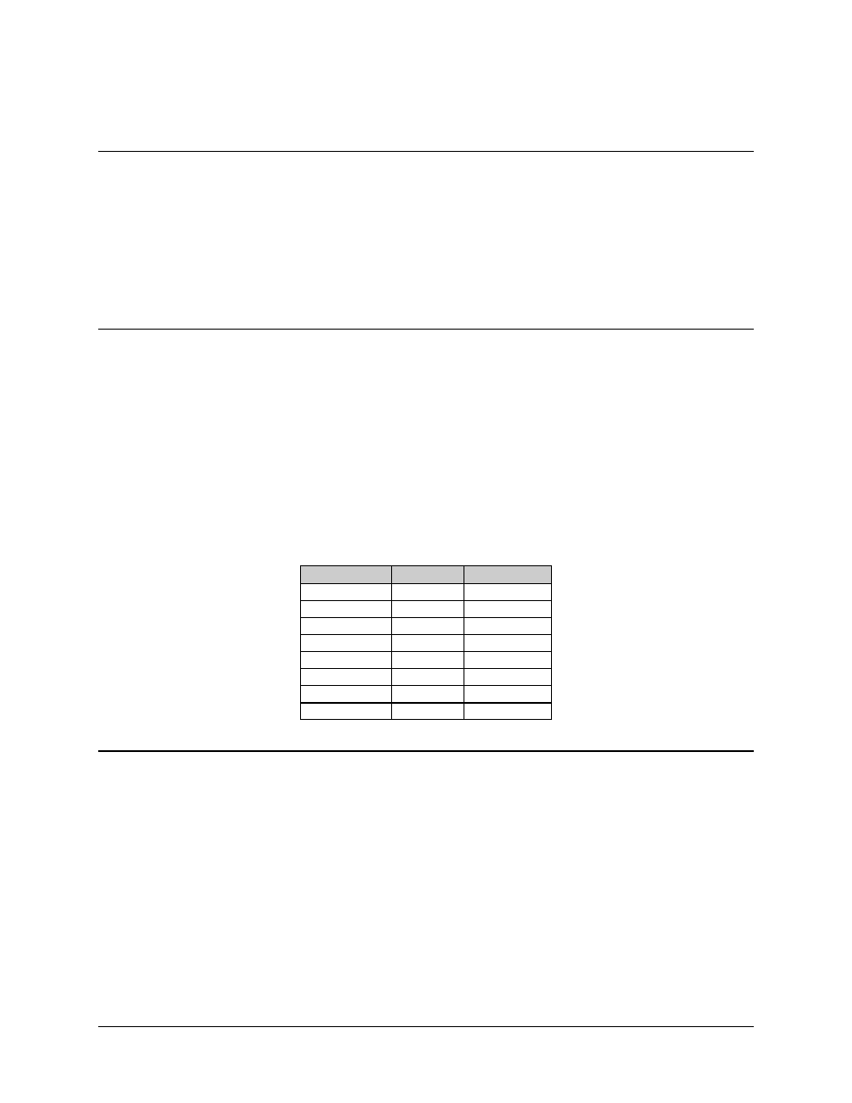
Option – Cable Part No. CA/0737 is offered by Comtech EFData. This 50-pin cable is
available in either straight hoods or right angle hoods. Refer to Table 2-1. This cable
includes two faults, Mod and Demod, pins 49 and 33. The modems will ground the two
pins when a No Fault condition exists. When either a Mod or Demod fault occurs, a line
will either Open, with the 50-pin cable pulled Off, or +5 VDC that is allowed from the
open collector fault circuit on the modem.
Table 2-1. 50-Pin Cable
Part No.
Length, ft
Type
CA/0737-2
2
Straight
CA/0737-4
4
Straight
CA/0737-4R
4
Right Angle
CA/0737-6
6
Straight
CA/0737-6R
6
Right Angle
CA/0737-8
8
Straight
CA/0737-8R
8
Right Angle
CA/0737-10
10
Straight
2.4.1.5
DSU JI CH to Prime Modem
Refer to Figure 2-5.
Option – Cable Part No. CA/0737 is offered by Comtech EFData.