Dsu data connections (j1 through j10), 6 dsu data connections (j1 through j10) – Comtech EF Data SMS-7000 User Manual
Page 54
Installation
SMS-7000 Modem Protection Switch
2–20
Rev. 3
2.6
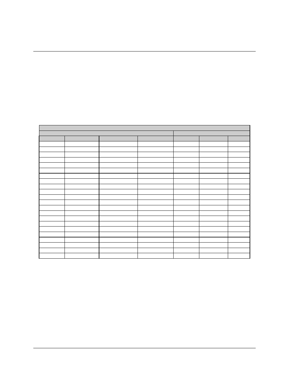
DSU Data Connections (J1 through J10)
There are 10 data cables between the modem face of the DSU and 10 possible modems
associated with the switch. Each of the eight prime modems has an associated data cable
connector, CH1 through CH8 (J1 through J8). The two backup modems are connected
with data cables to BU1 and BU2 (J9 and J10). The cable terminations are 50-pin male D
connectors. The signal/pin assignments, as they occur for each data configuration, are
listed in Table 2-3.
Table 2-3. DSU Data Connections (J1 through J10)
Signal Name
Overhead Type
SDM-100 and No Overhead
Pin #
IBS
IDR
D&I
EIA-422
V.35
EIA-232
1
GND
GND
GND
GND
GND
GND
2
GND
GND
GND
3
AGC-OUT
AGC-OUT
AGC-OUT
4
TXD-B
8K-TXO-A
5
TXD-A
8K-TXO-B
6
RXD-B
8K-RXO-A
7
RXD-A
8K-RXO-B
8
RS422RXO-A
BWO1-C
9
RS422RXO-B
BWO2-C
10
PRI-COM
BWO3-C
11
SEC-COM
BWO4-C
12
SCTE/TT-A
BWI-1
TT-A
SCTE-A
TT
13
SCTE/TT-B
BWI-2
TT-B
SCTE-B
14
RS422TXO-A
BWI-3
15
RS422TXO-B
BWI-4
16
DF-COM
17
DMA
18
G703_SDB
SD-B
DDI-B
19
EXC-B
EXC-B
EXC_B
EXC-B
EXC-B
20
G703_RDB
RD-B
IDO-B
21
SCT/ST-A
8K-TXC-A
ST-A
SCT A
ST
22
SCT/ST-B
8K-TXC-B
ST-B
SCT B