3 separate external mii management interfaces, 4 mii management timing specifications, Separate external mii management interfaces – BECKHOFF EtherCAT IP Core for Xilinx FPGAs v2.04e User Manual
Page 79: Mii management timing specifications, Table 34: mii management timing characteristics
Ethernet Interface
Slave Controller
– IP Core for Xilinx FPGAs
III-67
9.1.3
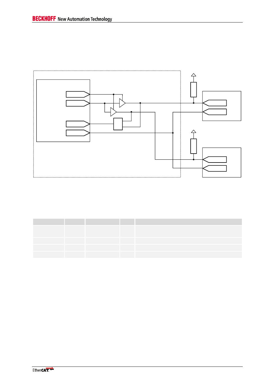
Separate external MII management interfaces
If two separate external MII management interfaces are to be connected to the single MII
management interface of the EtherCAT IP Core, some glue logic has to be added. Disable internal Tri-
State drivers for the MII management bus and combine the signals according to the following figure.
Take care of proper PHY address configuration: the PHYs need different PHY addresses.
EtherCAT IP Core
Ethernet PHY
MDIO_IN
MCLK
MDIO
MDC
4
K
7
V
CC I/O
Ethernet PHY
MDIO
MDC
4
K
7
V
CC I/O
MDIO_OUT
MDIO_ENA
&
FPGA
Figure 27: Example schematic with two individual MII management interfaces
9.1.4
MII management timing specifications
For MII Management Interface timing diagrams refer to Section I.
Table 34: MII management timing characteristics
Parameter
Min
Typ
Max
Comment
t
MI_startup
1.34 ms
Time between reset end and the first access of
via management interface
t
Clk
400 ns
MI_CLK period
t
Write
~ 25.6 µs
MI Write access time
t
Read
~ 25.4 µs
MI Read access time