5 opb slave interface, 1 interface, Opb slave interface – BECKHOFF EtherCAT IP Core for Xilinx FPGAs v2.04e User Manual
Page 116: Interface, Table 57: opb signals, Figure 56: opb signals
PDI Description
III-104
Slave Controller
– IP Core for Xilinx FPGAs
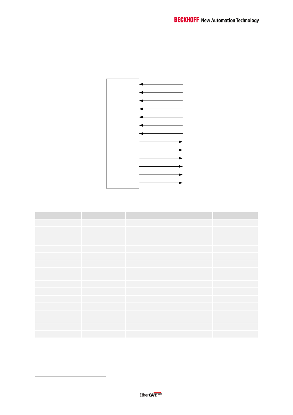
10.5 OPB Slave Interface
10.5.1 Interface
The OPB Slave PDI is selected during the IP Core configuration. The OPB interface is deprecated by
Xilinx and its support in the EDK software will be removed. The signals of the OPB interface are
14
:
EtherCAT
IP core
CLK
OPB
DBUS[0:31]
BE[0:3]
RNW
SEQADDR
SL_DBUS[0:31]
ABUS[0:31]
SL_XFERACK
SELECT
SL_ERRACK
SL_TOUTSUP
SL_RETRY
IRQ
Figure 56: OPB signals
Table 57: OPB signals
Signal
Direction
Description
Signal polarity
SELECT
IN
OPB Select
act. high
CLK
OPB
IN
OPB bus clock (rising edge
synchronous with rising edge of
CLK25 of the IP Core)
ABUS[0:31]
IN
OPB address bus
DBUS[0:31]
IN
OPB data bus
BE[0:3]
IN
OPB Byte Enable
act. high
RNW
IN
OPB Read/Write access
0: Write
1: Read
SEQADDR
IN
OPB sequential address
act. high
SL_DBUS[0:31]
OUT
Slave data bus
SL_XFERACK
OUT
Slave transfer acknowledge
act. high
SL_TOUTSUP
OUT
Slave timeout suppress
act. high
SL_ERRACK
OUT
Slave error acknowledge (not used,
always low)
act. high
SL_RETRY
OUT
Slave retry (not used, always low)
act. high
IRQ
OUT
Interrupt
act. high
Please refer to the On-Chip Peripheral Bus Architecture Specification from IBM (publication number
SA-14-2528-02) for details about the OPB bus
.
14
The prefix `PDI_OPB_` is added to the OPB interface signals for the IP Core interface.