3 led signals, 4 distributed clocks sync/latch signals, Led signals – BECKHOFF EtherCAT IP Core for Xilinx FPGAs v2.04e User Manual
Page 67: Distributed clocks sync/latch signals, Table 20: led signals, Table 21: dc sync/latch signals
IP Core Signals
Slave Controller
– IP Core for Xilinx FPGAs
III-55
8.3
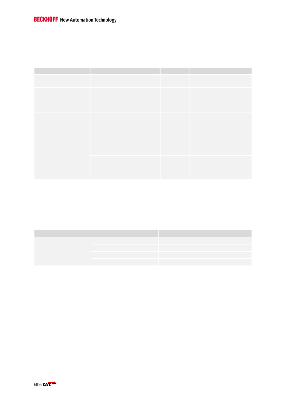
LED Signals
Table 20 lists the signals used for the LEDs. The LED signals are active high. All LEDs should be
green.
Table 20: LED Signals
Condition
Name
Direction
Description
LINK_ACT[0]
OUTPUT
Link/activity LED for
ethernet port 0
2 or 3 communication
ports
LINK_ACT[1]
OUTPUT
Link/activity LED for
ethernet port 1
3 communication ports
LINK_ACT[2]
OUTPUT
Link/activity LED for
Ethernet port 2
RUN_LED enabled
LED_RUN
OUTPUT
RUN LED for device
status.
Always 0 if RUN LED is
deactivated.
RUN_LED enabled and
Extended RUN/ERR
LED enabled
LED_ERR
OUTPUT
ERR LED for device
status.
LED_STATE_RUN
OUTPUT
Connect to RUN pin of
dual-color STATE LED,
connect LED_ERR to
ERR pin of STATE LED
NOTE: The application ERR LED and STATE LED can alternatively be controlled by a µController if required.
8.4
Distributed Clocks SYNC/LATCH Signals
Table 21 lists the signals used with Distributed Clocks.
Table 21: DC SYNC/LATCH signals
Condition
Name
Direction
Description
Distributed Clocks
enabled
SYNC_OUT0
OUTPUT
DC sync output 0
SYNC_OUT1
OUTPUT
DC sync output 1
LATCH_IN0
INPUT
DC latch input 0
LATCH_IN1
INPUT
DC latch input 1
NOTE: SYNC_OUT0/1 are active high/push-pull outputs.