3 asynchronous 8/16 bit µcontroller interface, 1 interface, 2 configuration – BECKHOFF EtherCAT IP Core for Xilinx FPGAs v2.04e User Manual
Page 104: Asynchronous 8/16 bit µcontroller interface, Interface, Configuration, Table 50: µcontroller signals, Figure 46: µcontroller interconnection
PDI Description
III-92
Slave Controller
– IP Core for Xilinx FPGAs
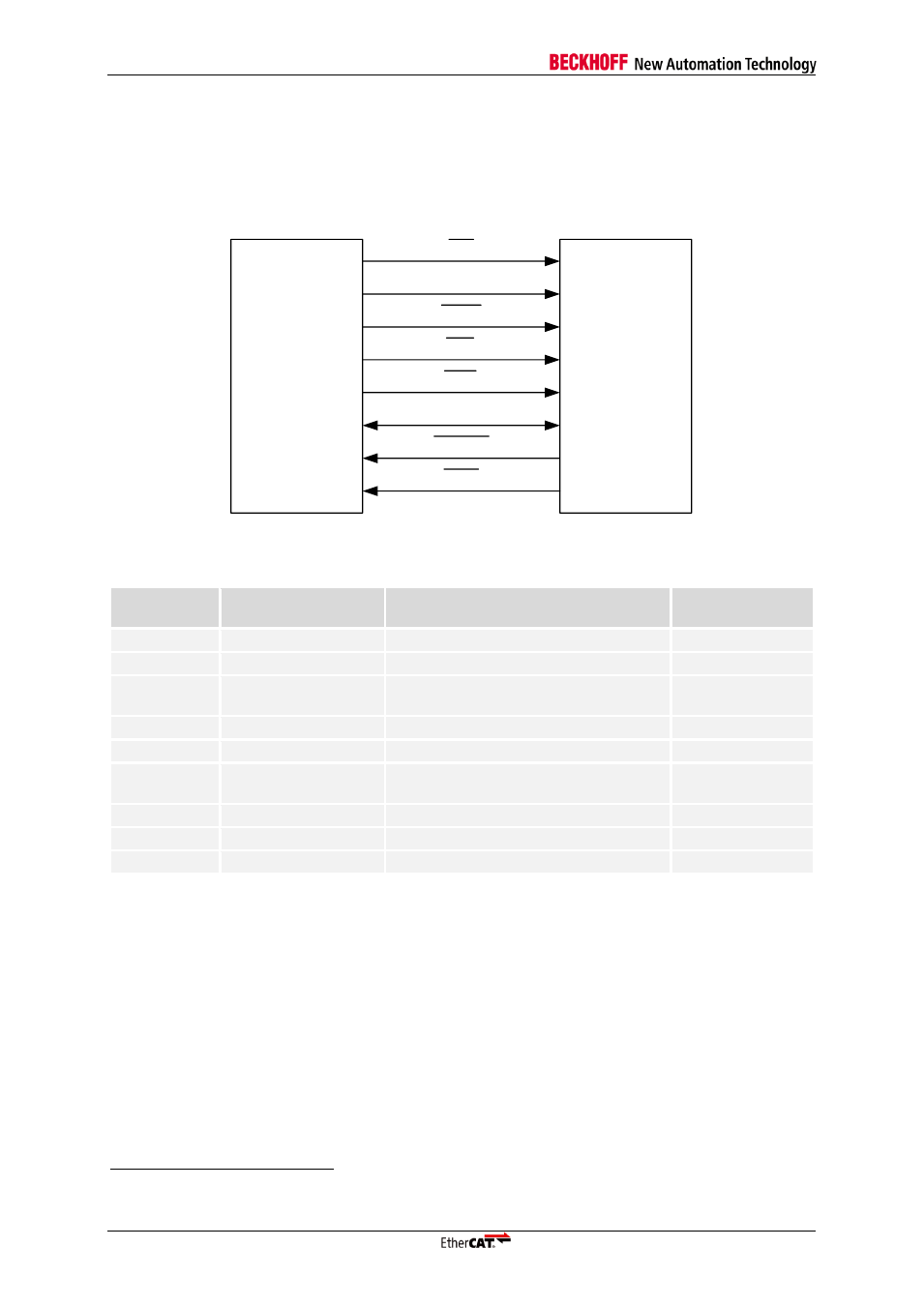
10.3 Asynchronous 8/16 bit µController Interface
10.3.1 Interface
The asynchronous µController interface uses demultiplexed address and data busses. The
bidirectional data bus can be either 8 bit or 16 bit wide. The signals of the asynchronous µController
interface of EtherCAT devices are
8
:
8/16 bit
µController
(async)
CS
ADR
BHE
DATA
BUSY
EtherCAT
device
IRQ
RD
WR
Figure 46: µController interconnection
9
Table 50: µController signals
Signal
async
Direction
Description
Signal polarity
CS
IN
(µC → ESC)
Chip select
Typical: act. low
ADR[15:0]
IN
(µC → ESC)
Address bus
Typical: act. high
BHE
IN
(µC → ESC)
Byte High Enable (16 bit µController
interface only)
Typical: act. low
RD
IN
(µC → ESC)
Read command
Typical: act. low
WR
IN
(µC → ESC)
Write command
Typical: act. low
DATA[15:0]
BD
(µC
↔ ESC)
Data bus for 16 bit µController
interface
act. high
DATA[7:0]
BD
(µC
↔ ESC)
Data bus for 8 bit µController interface
act. high
BUSY
OUT
(ESC → µC)
EtherCAT device is busy
Typical: act. low
IRQ
OUT
(ESC → µC)
Interrupt
Typical: act. low
Some µControllers have a READY signal, this is the same as the BUSY signal, just with inverted
polarity.
10.3.2 Configuration
The 16 bit asynchronous µController interface is selected with PDI type 0x08 in the PDI control
register 0x0140, the 8 bit asynchronous µController interface has PDI type 0x09. It supports different
configurations, which are located in registers 0x0150
– 0x0153.
8
The prefix `PDI_uC_` or `PDI_uC_8` is added to the µController signals if the EtherCAT IP Core is used.
9
All signals are denoted with typical polarity configuration.