2 rmii interface, Rmii interface, Table 24: phy interface rmii – BECKHOFF EtherCAT IP Core for Xilinx FPGAs v2.04e User Manual
Page 71
IP Core Signals
Slave Controller
– IP Core for Xilinx FPGAs
III-59
8.5.2
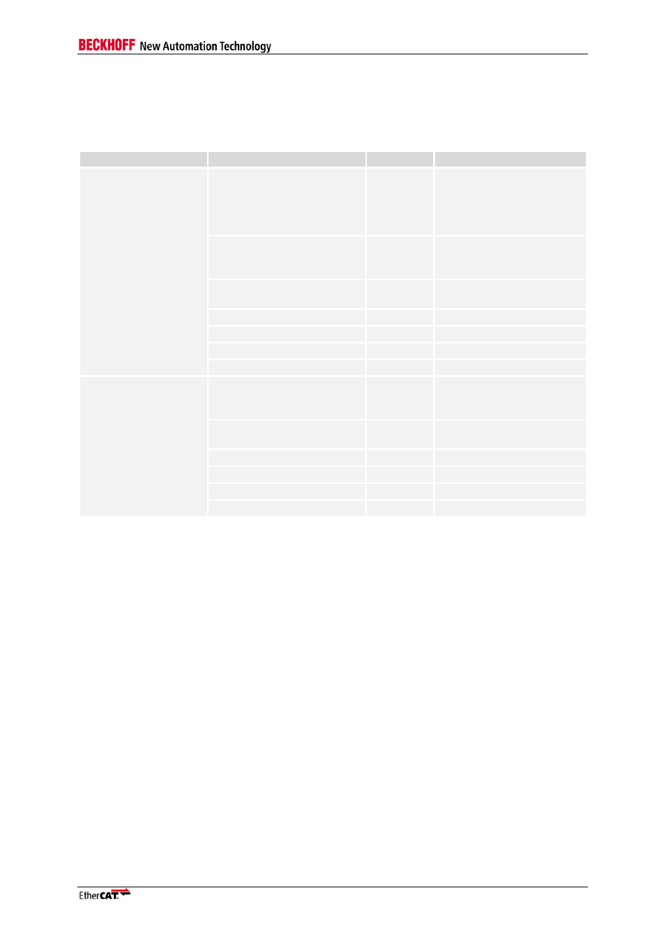
RMII Interface
Table 24 lists the signals used with RMII.
Table 24: PHY Interface RMII
Condition
Name
Direction
Description
Port0 = RMII
CLK50
INPUT
50 MHz reference clock
signal from PLL (rising edge
synchronous with rising
edge of CLK100), also
connected to PHY
nRMII_LINK0
INPUT
0: 100 Mbit/s (Full
Duplex) link at port 0
1: no link at port 0
RMII_RX_DV0
INPUT
Carrier sense/receive data
valid port 0
RMII_RX_DATA0[1:0]
INPUT
Receive data port 0
RMII_RX_ERR0
INPUT
Receive error port 0
RMII_TX_ENA0
OUTPUT
Transmit enable port 0
RMII_TX_DATA0[1:0]
OUTPUT
Transmit data port 0
Port1 = RMII
nRMII_LINK1
INPUT
0: 100 Mbit/s (Full
Duplex) link at port 1
1: no link at port 1
RMII_RX_DV1
INPUT
Carrier sense/receive data
valid port 1
RMII_RX_DATA1[1:0]
INPUT
Receive data port 1
RMII_RX_ERR1
INPUT
Receive error port 1
RMII_TX_ENA1
OUTPUT
Transmit enable port 1
RMII_TX_DATA1[1:0]
OUTPUT
Transmit data port 1