2 planar leds, 1 debug leds, Table 3-1 – Artesyn iVPX7225 Installation and Use (April 2015) User Manual
Page 57: Planar leds, Controls, leds and connectors
Controls, LEDs and Connectors
iVPX7225 Installation and Use (6806800S11C)
38
3.2
Planar LEDs
3.2.1
Debug LEDs
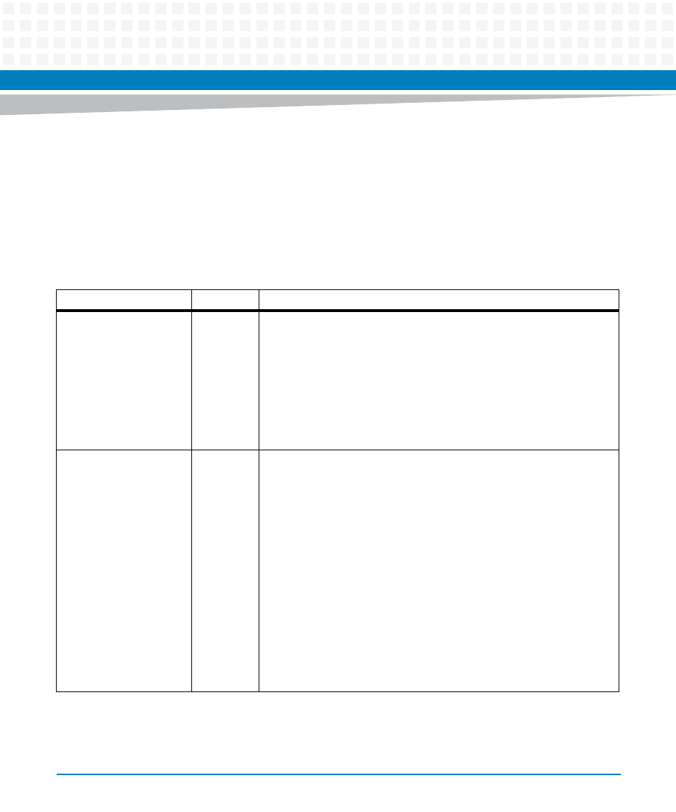
iVPX7225 provides two debug LEDs on the secondary side of the PCB.The following table
details the LED status descriptions:
Table 3-1 Planar LEDs
LED
Color
Description
Power Fail LED
(RefDes D7)
Red
Persistently OFF - All onboard power supplies are good and stable. The
power-OK signal (SYS_PWROK) is also asserted.
Persistently ON- At least one onboard power supply is failing.
Blinking (0.25 seconds ON, 0.25 seconds OFF) - Board has power shut
down but also indicates that all the onboard power supplies are up and
stable. This will also indicate that the board is waiting for the platform
reset signal PLT_RST_L to de-assert.
User LED
(RefDes D23)
Bicolor
Yellow and
Green
Green is persistently ON - Indicates that the platform reset signal
(PLTRST_L) is de-asserted and the board starts to boot up.
Green is blinking - Indicates that the CPU PROCHOT# signal is asserted.
The CPU has reached its maximum junction temperature. If PROCHOT# is
persistently asserted, the Green LED will blink in a periodic manner (0.25
seconds ON, 0.25 seconds OFF).
Yellow is ON - Indicates that the on-board NAND Flash or SATA device is
being accessed (example: OS is booting up from these devices).
Yellow is blinking (0.25 seconds ON, 0.25 seconds OFF) - Indicates that
the CPU THERMTRIP# signal is asserted and the CPU will stop all
execution.
Green and Yellow are alternately blinking - Indicates the CPU has
experienced a catastrophic error and cannot continue to operate.