Fpga registers – Artesyn iVPX7225 Installation and Use (April 2015) User Manual
Page 158
FPGA Registers
iVPX7225 Installation and Use (6806800S11C)
139
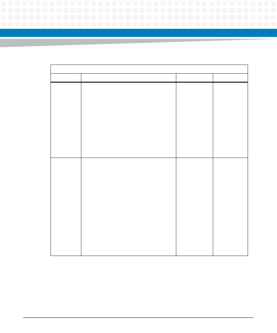
2
Parity Error (PE) indicator
When PE is set, it indicates that the parity of
the received data character does not match
the parity selected in the LCR (bit 4). PE is
cleared every time the CPU reads the contents
of the LSR. In the FIFO mode, this error is
associated with the particular character in the
FIFO to which it applies. This error is revealed
to the CPU when its associated character is at
the top of the FIFO:
1: Parity error occurred
0: No parity error
0
R
3
Framing Error (FE) indicator
When FE is set, it indicates that the received
character did not have a valid (set) stop bit. FE
is cleared every time the CPU reads the
contents of the LSR. In the FIFO mode, this
error is associated with the particular
character in the FIFO to which it applies. This
error is revealed to the CPU when its
associated character is at the top of the FIFO.
The ACE tries to resynchronize after a framing
error. To accomplish this, it is assumed that
the framing error is due to the next start bit.
The ACE samples this start bit twice and then
accepts the input data:
1: Framing error occurred
0: No framing error
0
R
Table 7-53 Line Status Register (LSR) (continued)
IO Address: Base +5
Bit #
Description
Default
Access