1 super io configuration registers, 1 entering the configuration state, 2 exiting the configuration state – Artesyn iVPX7225 Installation and Use (April 2015) User Manual
Page 140: Table 7-29, Super io configuration index register, Table 7-30, Super io configuration data register, Fpga registers
FPGA Registers
iVPX7225 Installation and Use (6806800S11C)
121
7.2.1
Super IO Configuration Registers
After a LPC Reset (PCI_RST_ is asserted) or “Power Up Reset” the Super IO is in the Run Mode
with the UART units disabled. They may be configured using the LPC IO Address Range SIW
(INDEX and DATA) by placing the Super IO into Configuration Mode. The BIOS uses these
configuration addresses to initialize the logical devices at POST. The INDEX and DATA
addresses are effective only when the Super IO is in the Configuration State. When the Super
IO is not in the Configuration State, reads return 0xFF and write data is ignored.
7.2.1.1
Entering the Configuration State
The device enters the Configuration State by the following contiguous sequence:
1. Write 80H to Configuration Index Port.
2. Write 86H to Configuration Index Port.
7.2.1.2
Exiting the Configuration State
The device exits the Configuration State by the following contiguous sequence:
1. Write 68 to Configuration Index Port.
2. Write 08 to Configuration Index Port.
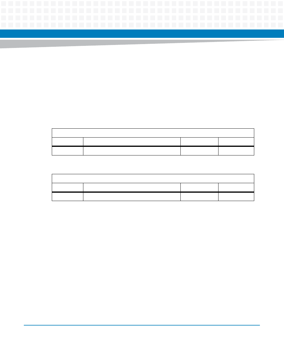
Table 7-29 Super IO Configuration Index Register
LPC I/O Address: 0x4E
Bit #
Description
Default
Access
7:0
Index Configuration Index
0xFF
LPC: R/W
Table 7-30 Super IO Configuration Data Register
LPC I/O Address: 0x4F
Bit #
Description
Default
Access
7:0
DATA Configuration data
0xFF
LPC: R/W