Maytag Atlantis User Manual
Page 97
Attention! The text in this document has been recognized automatically. To view the original document, you can use the "Original mode".
SECTION 10. ELECTRICAL SCHEMATICS
An electrical schematic is folded and placed inside the control console of each washer. It
can be accessed by removing the control console (Page 4-1).
The schematic diagram provides vital information needed to check a circuit and pinpoint
a malfunctioning electrical component (Chapter 9).
The schematic diagram contains the following:
* Connection Diagram
* Cycle Sequence Chart
• Motor Harness Connector Identification
• АТС Harness Connector Identification
(If applicable to the model).
A thorough understanding of the information available on the schematic diagram is a pre
requisite for quick and accurate troubleshooting.
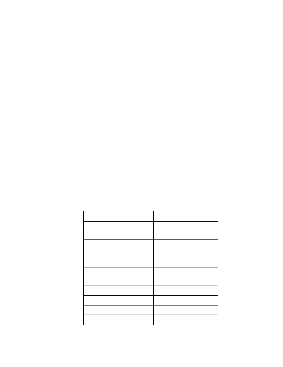
The following electrical schematics are illustrated for the following models:
MODEL NUMBER
PAGE NUMBER
MAV4057
10-2
MAV4500
10-2
MAV5000
10-3
MAV5057
10-4
MAV6000
10-5
MAV6057
10-6
MAV7000
10-7
MAV7057
10-8
MAV8000
10-9
MAV8057
10-10
MAV8500
10-11
16009485-01
Section 10. Electrical Schematics
10-1
©1999 Maytag Appliances Sales Company