Suspension housing, Tub braces, Suspension springs – Maytag Atlantis User Manual
Page 52: Suspension housing -2, Tub braces -2, Suspension springs -2
Attention! The text in this document has been recognized automatically. To view the original document, you can use the "Original mode".
SUSPENSION HOUSING
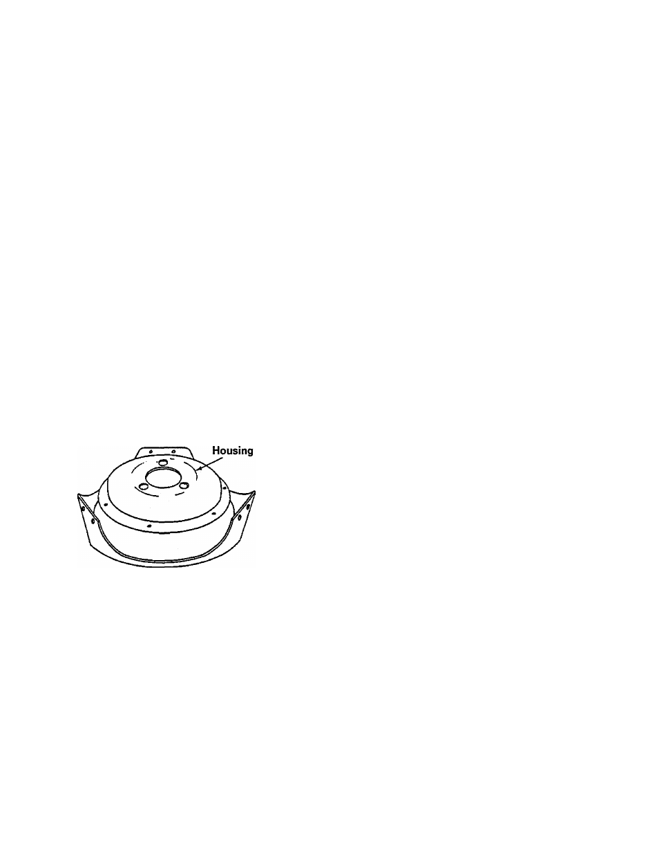
The suspension housing is fabricated of heavy
gauge steel. It rests on the raised domelike
area in the center of the base and supports
the weight of the transmission, outer tub, and
spin basket (Figure 6-2).
The underside of the suspension housing pro
vides mounting for the snubber pad and also
houses the brake assembly (Figure 2-2).
The bottom of the housing has been formed
into a spherical configuration and, along with
the snubber, rides on the domed area of the
base which allows the housing to move freely
in all directions.
The top of the suspension housing is attached
to the lower bearing assembly with three
mounting screws. These screws thread from
the underside of the suspension housing dome
into the die-cast bearing housing.
3. Remove the brake assembly as detailed in
Section 7.
4. Remove screws securing housing to the
lower bearing assembly.
TUB BRACES
The tub braces are attached at the top to the
tub support, and to the suspension housing
at the bottom. The tub braces are located
behind iic\e tub support and suspension hous
ing where large, thread forming screws are
driven directly into the braces to secure them.
NOTE: Should a tub brace mounting screw
hole become stripped, a nut can be installed
on the thread forming screw.
The extended end of the suspension spring
fits through an extruded hole in the tub brace
just below the mounting screws.
/
Suspension
Figure 6-2
Service to the suspension housing, other than
replacing it, is limited to replacing one of the
other components that mount to the housing.
The replacement procedures for these com
ponents are detailed in the Transmission Sec
tion of this manual.
REMOVAL
1. Disconnect power to the unit.
2. Remove the transmission assembly as de
tailed in Section 7.
SUSPENSION SPRINGS
The suspension springs hold the entire wash
unit in firm contact with the base. To reduce
wear and prevent squeaks; grease has been
applied to the friction points of the springs.
REMOVAL
The suspension springs can be removed and
replaced by using the spring tool, part num
ber 22002922 as follows:
1. Disconnect power to the unit.
2. Remove the front panel and rear access
panel.
3. Pull or block the tub in the direction of the
spring to be removed.
NOTE: Removing the tub top will allow the
tub to travel further and extend the spring less.
16009485-01
©1999 Maytag Appliances Sales Company
Section
6
. Suspension System
6-2