Motor, Motor mounting, Motor -9 – Maytag Atlantis User Manual
Page 84: Motor mounting -13
Attention! The text in this document has been recognized automatically. To view the original document, you can use the "Original mode".
Motor
If the motor runs in one direction but will not
reverse, the problem is in the timer or wiring
harness, not in the motor. The same motor
components are used when the motor runs
in either direction; the only change is in the
electrical circuitry feeding the start winding
which is controlled by the timer and related
wires.
A two conductor test cord which has two fe
male spade connector terminals on each con
ductor is needed to test the motor operations
(tool number 038183).
To test a motor, connect the two spade con
nectors on one side of the cord to terminals 1
and 4 on the starting switch and the two con
nectors on the other side of the cord to the
starting switch terminals 2 and 3.
To check the slow speed operation, change the
lead on terminal 3 to terminal 5. Be sure to
test the motor in its normal vertical position.
If the motor will not start, or if it starts but
does not attain normal speed, check the op
eration of the external motor switch, replace
the motor.
NOTE: Normal resistance of the motor wind
ings should be:
NORMAL SPEED
1.3 OHMS
SLOW SPEED
2.3 OHMS
START
3.1 OHMS
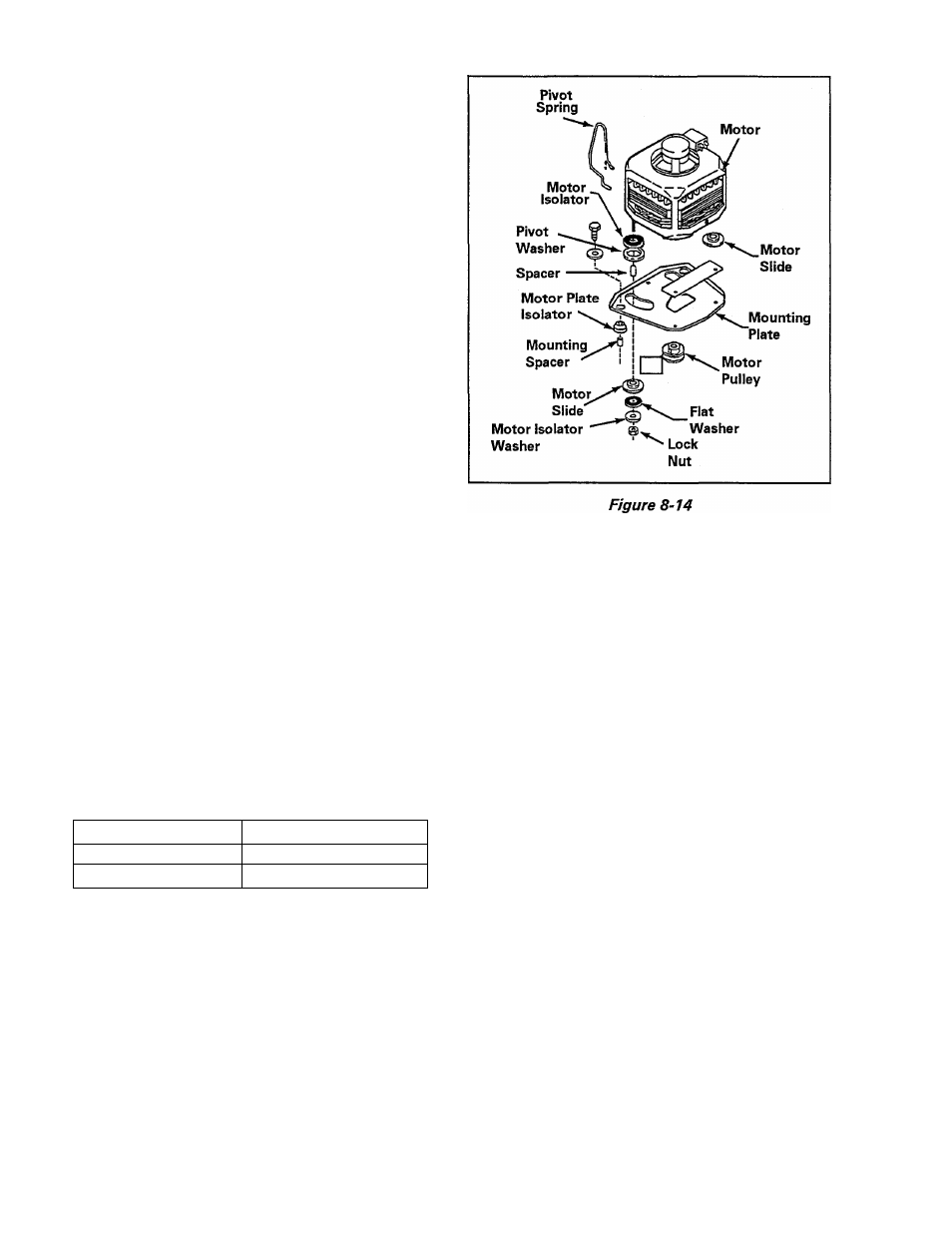
MOTOR MOUNTING
The motor mount system consists of a motor
and mounting plate assembly as shown in
(Figure 8-14).
Assembled to the motor studs and secured
by locknuts are rubber isolators and washers
which sandwich nylon washers and slides
through slots in the mounting plate. A nylon
slide is attached to the motor bottom, and a
pivot spring installs between the motor and
mounting plate.
In operation, the nylon washers and slides ride
in the slots in the mounting plate, and the slide
rides the mounting plate. The motor is free
to pivot in either direction and the pivot spring
ensures proper belt tension on the motor
pulley.
The mounting plate has rubber mounting
cushions assembled to its rear corners, and
the entire assembly is mounted to the washer
base by two (2) large hex head screws.
REMOVAL
1. Disconnect power to the unit.
2. Tip washer and remove drive belt.
3. Remove the front panel.
,y
16009485-01
Section 8. Electrical Components & Testing
©1999 Maytag Appliances Sales Company
8-14