Motor and switch operation – Maytag Atlantis User Manual
Page 82
Attention! The text in this document has been recognized automatically. To view the original document, you can use the "Original mode".
LINE
MOTOR
COMMON
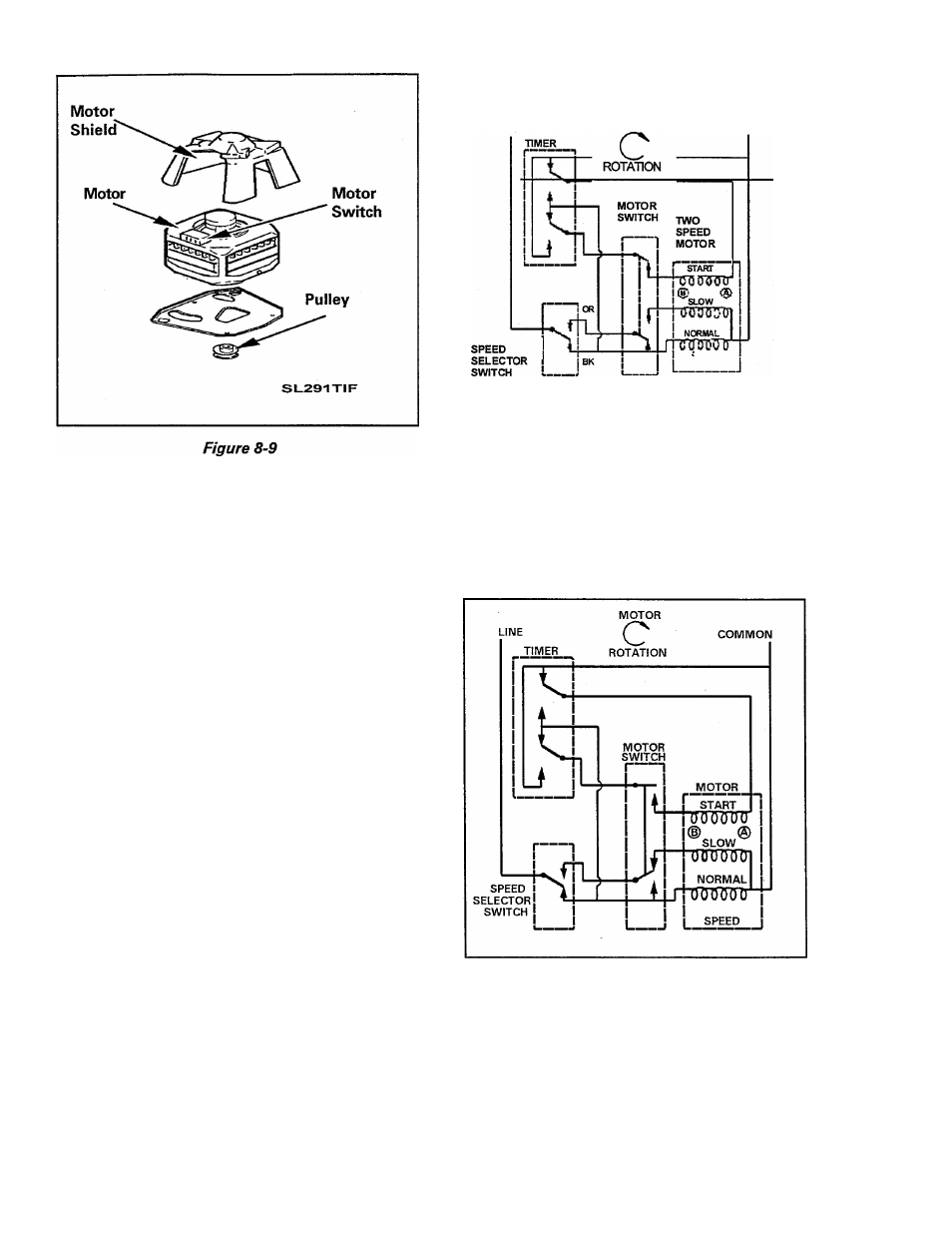
Figure 8-10
Motor and Switch Operation
The polarity of the magnetic field of the start
winding, in relation to the magnetic field of
the run winding, determines the direction of
the rotation of the motor.
The timer is used to reverse the polarity of the
start winding field.
Side A of the start winding is connected to
the common side, B is connected to the line
through the motor switch. The speed selec
tor switch is set for normal speed operation
(Figure 8-10).
As the motor starts running, the motor switch
moves opening the start winding circuit. The
motor is running on the normal speed wind
ing in the direction indicated (Figure 8-11).
Figure 8-11
16009485-01
The timer selection has been changed, now
side A of the start winding is connected to the
line; side B is connected to the common side
through the motor switch. The speed selec
tor switch is set for slow speed operation.
Section 8. Electrical Components & Testing
©1999 Maytag Appliances Sales Company
8-12