Water inlet flume, Air bell, Water inlet flume -2 air bell -2 – Maytag Atlantis User Manual
Page 42
Attention! The text in this document has been recognized automatically. To view the original document, you can use the "Original mode".
WATER INLET FLUME
HOSES
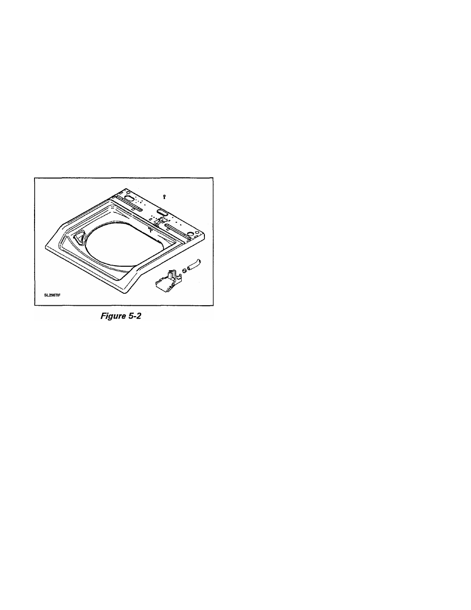
The molded plastic water inlet flume consists
of an upper and lower section that has been
snap-locked together.
The flume is located on the rear underside of
the washer top assembly. The flume fits flush
with the top opening and is secured to the top
by one mounting screw, accessed through the
control console. An inlet hose from the wa
ter mixing valve connects to the flume nozzle.
AIR BELL
Water Supply Inlet Hoses
Two (2) water inlet hoses attach from hot and
cold water supply lines to their respective
nozzles on the water mixing valve. They are
secured at both ends with threaded couplings.
Flume Inlet Hose
The flume inlet hose attaches the water mix
ing valve to the water inlet flume. It is secured
at both ends with spring type hose clamps.
Pressure Switch Hose
The pressure switch hose is made of soft plas
tic tubing and fits snugly over the water level
switch nipple at one end, and the air bell nipple
at the other. A clamp on the inner cabinet rear
positions the hose, and a pad prevents the
hose from contacting the back of the cabinet
during operation. The hose is installed with
its ends seated against the switch and air bell
bodies, and is secured at the tub ends with a
spring type hose clamp.
Tub to Pump Hose
A polypropylene air bell and nipple assembly
have been thermally welded to the lower, outer
tub, rear. One end of the pressure switch hose
connects to the air bell nipple and the other
end is attached to the water level switch.
As the water level rises in the tub, it com
presses the air in the air bell and the attached
hose. The compressed air inside the hose will
activate the pneumatically operated water
level switch when the selected water level has
been reached. When the air pressure is low
ered during the drain cycle, the switch will
reset.
N OTE ; When reinstalling the pressure switch
hose, make sure the system is free of air leaks
and water in the hose or an overflow condi
tion will occur.
The tub to pump hose attaches from the drain
outlet on the tub to the pump inlet. It is se
cured at each end with a spring-type hose
clamp.
Drain Hose
The drain hose attaches the pump outlet to
the drain standpipe. It is secured to the pump
with a spring-type hose clamp.
16009485-01
Section 5. Water Related Components
5-2
©1999 Maytag Appliances Sales Company