General information, Clutch assembly, General information -1 clutch assembly -1 – Maytag Atlantis User Manual
Page 21
Attention! The text in this document has been recognized automatically. To view the original document, you can use the "Original mode".
SECTION 2. OUTLINE OF MECHANICAL OPERATION
GENERAL INFORMATION
NOTE: The rotation directions, stated in this
outiine, view the component from its oui-
iev end.
The washer utilizes a reversible type motor
which turns clockwise during the agitate
cycle and counterclockwise during the spin
cycle.
A single belt is used to transmit power from
the motor pulley to the drive and pump pul
leys.
The transmission drive pulley, which drives the
transmission drive shaft and hub assembly,
and the pump pulley which drives the pump
impeller, are in operation whenever the mo
tor is running.
The transmission assembly converts the
power from the motor to either drive the agi
tator or spin the basket. The direction the
clutch assembly rotates determines which
action takes place.
CLUTCH ASSEMBLY
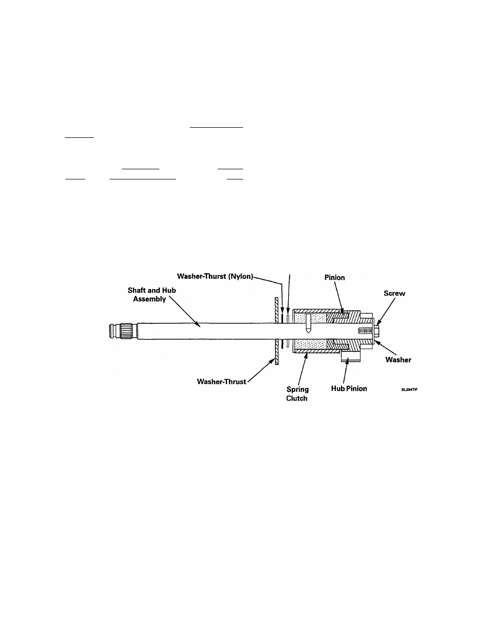
Washer-Thrust Hub
Figure 2-1
CLUTCH ASSEMBLY
The clutch assembly (Figure 2-1) consists of
the drive shaft and hub assembly, clutch
spring, and input pinion with gear lock assem
bly. The gear lock mechanism is part of the
input pinion. The drive shaft serves only as a
bearing surface for the drive pinion to revolve
on. No direct drive is imparted from the shaft
directly to the pinion. The inside diameter of
the clutch spring is designed so that when the
drive shaft is driven in a clockwise direction.
the clutch spring tightens on the two hubs and
becomes a positive link between them. When
the drive shaft hub runs counterclockwise, the
clutch spring relaxes in an override situation.
While in override, or relaxed position, the
clutch spring still maintains a drive link be
tween the two hubs. The override tension, or
torque, is used to drive the spin basket. The
gear lock mechanism consists of two "wings"
that project out from the input pinion.
16009485-01
©1999 Maytag Appliances Sales Company
Section 2. Operation
2-1