Lid switch, Lid switch -17 – Maytag Atlantis User Manual
Page 89
Attention! The text in this document has been recognized automatically. To view the original document, you can use the "Original mode".
LID SWITCH
Models MAV4057/4500/5000/5057
8000/8057
WATER SELECTOR SWITCH
POSITION
CIRCUIT
H-C
BK*-PK*
w-w
BK*-PU*, OR**-BU**,
BK*-PK*
w-c
BK*-PK*, BK*-PU*
c-c
BK*-PU*
* 1/4" Terminals -
» 3/16“ Terminals
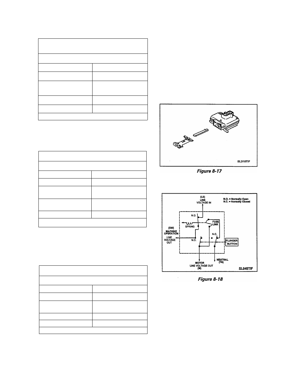
The lid switch assembly is designed to inter
rupt voltage to the wash motor in the event
the lid is raised. The switch is a single pole,
throw type with normally open contacts.
The normally OPEN set of contacts in the
switch are held CLOSED by a fusible link
(Figure 8-18).
Models MAV6000/6057/7000/7057
WATER SELECTOR SWITCH
POSITION
CIRCUIT
H-C
BK*-PK*, BU**-OR**
w-w
BK*-PU*, BK*-OR**
BK*-PK*
w-c
BK*-PK*, BK*-PU*,
BU**-OR**
c-c
BK*-PU*, BU**-OR**
* 1/4" Terminals
** 3/16" Terminals
Models MAV8500
WATER SELECTOR SWITCH
POSITION
CIRCUIT
H-C
BK*-RD*
w-w
BK*-RD*, BU**-RD**
BU**-OR**
w-c
BK*-RD*, BU'^*-RD**
c-c
BU**-RD**
* 1/4" Terminal
** 3/16" Terminal
Should a switch malfunction, current is di
rected through the fuse link causing it to break
down. Once the fuse link opens, the formed
contact spring arm opens and the power to
the machine is permanently disabled. Note,
the schematic representation in (Figure 8-19).
16009485-01
©1999 Maytag Appliances Sales Company
Section 8. Electrical Components & Testing
8-19