Example, Timer sequence chart, Using the time sequence chart – Maytag Atlantis User Manual
Page 73: Timer sequence chart -3
Attention! The text in this document has been recognized automatically. To view the original document, you can use the "Original mode".
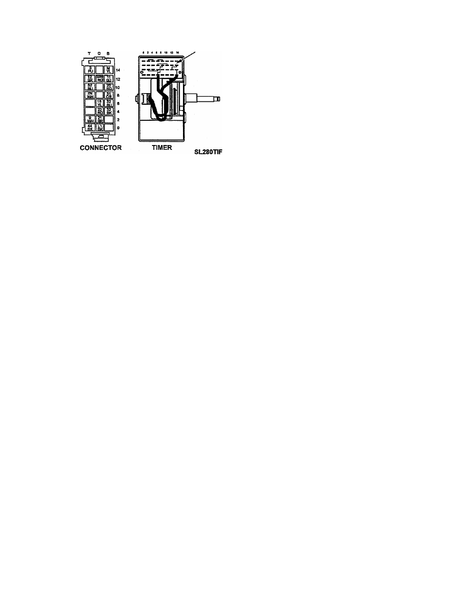
TERMINAL BOARD
Figure 8-1
vision, indicates the travel of the timer through
a cycle.
The heavy black lines to the right of the termi
nal column indicate a closed contact. If the
contact is open, there is a break in the heavy
black line.
EXAMPLE
REMOVAL
Cam 0 shows the switch arm dosed, mak
ing contact between Line 1 and wire 44
from increments 4 through 18. This cir
cuit is the cam controlled ON/OFF switch
in the timer and at increment 19 it opens,
shutting the machine off (Figure 8-2).
Timer removal procedures are detailed in Sec
tion 4 under Control Pane! Assembly Re
moval.
Timer Testing
The timer can be tested by using an ohmme-
ter and the Timer Sequence Chart as detailed
in the following.
TIMER SEQUENCE CHART
The following chart depicts a typical Timer
Sequence Chart which can be found on the
schematic diagram. It denotes the internal
timer contacts which are opened and/or
closed by the timer cam switches at any in
terval during a machine cycle.
Listed down the side of the chart at the left,
each contact in the timer is identified as be
ing controlled by a particular cam. The func
tion of each contact and its terminal designa
tion is also indicated.
Across the bottom of the chart are the vari
ous machine cycles available for selection, and
the timer increments at which the cycle be
gins and ends. The increment, or degree di-
Using the Time Sequence Chart
The sequence chart used in conjunction
with an ohmmeter can be quite effective when
attempting to verify or diagnose problems in
the timer, wiring, or other electrical parts.
In order to establish exactly which electrical
components should be operating during any
given time throughout the various machine
cycles, it is only necessary to determine what
particular cycle and phase of the cycle you
are interested in.
Once the cycle and phase have been ascer
tained, locate these along with the increment
at the bottom of the Timer Sequence Chart.
When the cycle, phase and increment are lo
cated, follow the increment from the bottom
to the top of the chart noting which timer con
tacts are involved in the area of concern.
Once the timer contacts have been deter
mined, the electrical circuits involved can be
traced on the connection diagram by incre
ment or by phase, if necessary.
16009485-01
©1999 Maytag Appliances Sales Company
Section 8. Electrical Components & Testing
8-3