Water level switch, Water level switch operation, Important – Maytag Atlantis User Manual
Page 86: Testing the water level switch, Water level switch -14
Attention! The text in this document has been recognized automatically. To view the original document, you can use the "Original mode".
WATER LEVEL SWITCH
Water Level Switch Operation
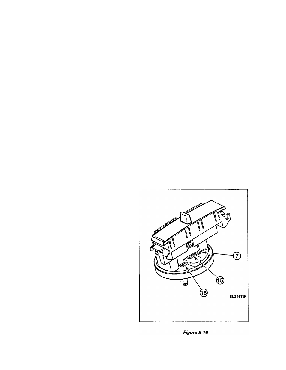
The water level switch is secured to the con
trol console by means of two locking tabs on
the switch body [Figure 8-16).
The water level switch is operated by a col
umn of air that becomes trapped in the pres
sure switch hose. This hose is connected be
tween the diaphragm section of the switch
and air bell which is located on the lower por
tion of the tub. As water enters the tub, a
small amount enters the pressure switch hose
thereby trapping air in the hose. As the water
level increases in the tub, this column of air
becomes compressed and exerts pressure on
the water level switch diaphragm. When the
proper water level is reached the diaphragm
actuates a single pole, double throw switch in
the water level switch assembly.
The water level switch is quite sensitive and
requires only about 0.6 RS.I. to activate it at
the maximum fill position.
It is most important that the hose connections
to the switch diaphragm and air bell nipple
be airtight, as the smallest air leak will cause
erratic operation.
__ IMPORTANT_____________________
The water level switch is adjusted and
sealed at the manufacturing source and no
adjustments should be made in the field.
Whenever the hose is removed from the wa
ter level switch or the air bell nipple, DO NOT
reconnect the hose until all water has been
drained from the tub. To ensure proper op
eration of the water level switch, the hose
MUST NOT have any water in it when rein
stalled on the switch. When reconnecting the
hose, be sure to slip it over the nipple(s) as far
as possible.
The circuitry of the machine is designed to
put the switch in control of the water mixing
valve or the timer motor and drive motor dur
ing various phases of the wash cycle.
During the fill cycle, the switch makes a cir
cuit between terminals 7 and 15 which ener
gizes the mixing valve circuit(s). (Figure 8-
16) When the switch is activated, it opens the
circuit between terminals 7 and 15 which
shuts off the water, and closes a circuit be
tween terminals 7 and 16 which energizes the
timer motor and drive motor.
Testing the Water Level Switch
The water level switch can be accessed as pre
viously detailed in Section 4 under Control
Pane! Disassembly. It can be tested using an
ohmmeter and executing the following.
16009485-01
Section 8. Electrical Components & Testing
©1999 Maytag Appliances Sales Company
8-16