Arm-2, Auxiliary relay module – Potter PFC-4410RC User Manual
Page 97
97
PFC-4410RC • 5403550 • REV Q • 11/12
BLACK
CONNECT ARM-2 TO
OUTPUT CIRCUIT
RED
PFC-4410RC OUTPUT TERMINALS
DWG# 977-2
Stock number: 3004725
UL Listed: For use with the PFC-4410RC Series
Dimensions: 2 1/4" x 3 1/2" x 3"
Weight: .315 lb.
Assembly: Socketed relay in plastic mounting track
Power Requirements: 40mA at 24VDC
Contact Ratings:
Each relay has DPDT contacts,
Rated at 7.5 amps resistive,
120VAC, 30VDC
MFG. #5400977 - REV N
9/08
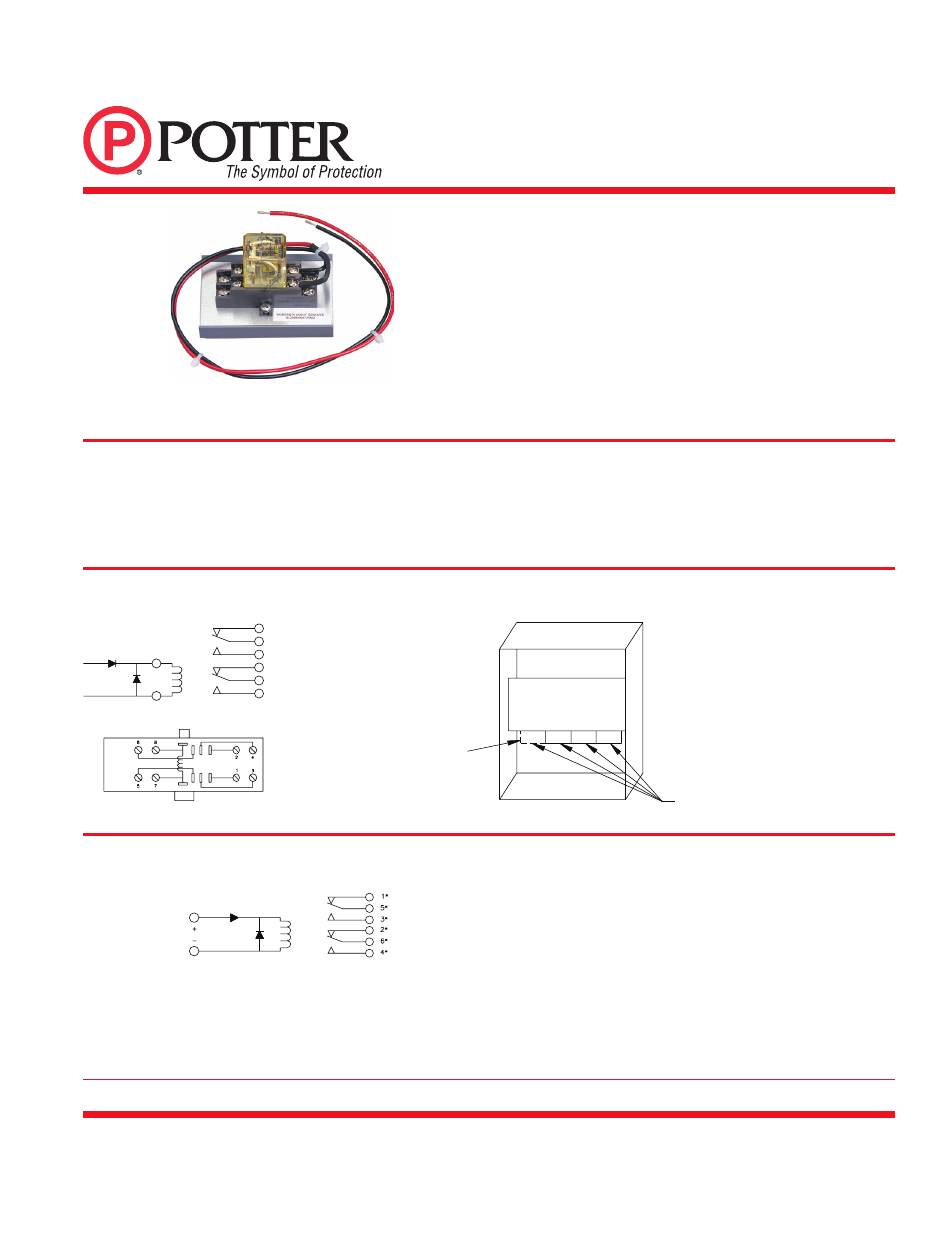
ARM-2
AUXILIARY RELAY MODULE
The ARM-2 Auxiliary Relay Module is a UL listed option when factory
installed in the Potter PFC-4410RC Series.
When the ARM-2 is used the additional power required for this relay
module must be subtracted from the total circuit current available.
See PFC-4410RC Manual #5403550. The ARM-2 Auxiliary Relay
Module is a non-supervised DPDT Relay designed to be activated
PAGE 1 OF 1
PRINTED IN USA
Wiring
Placement In PFC-4410RC Series Control Unit
Potter Electric Signal Company, LLC • St. Louis, MO • Cust Service: 866-572-3005 • Tech Support: 866-956-0988 • Canada 888-882-1833
• www.pottersignal.com
18” WIRE LEADS
FURNISHED FOR
RELAY COIL
RED
BLACK
7
8
RELAY SHOWN DE-ENERGIZED
* NUMBERS REFER TO
SOCKET TERMINALS
NOT RELAY PINS.
1*
5*
3*
2*
6*
4*
FOURTH RELAY FOR PFC-4410
DWG# 977-1
MAIN PC BOARD MODULE
ARM-2 RELAYS
TO
P VIEW
SOCKET
TERM.
NUMBERS
Notes:
1. * Numbers refer to socket terminals not relay pins.
2. Auxiliary relay operation is determined by programming of the PFC-4410RC Series panel. Consult the appropriate manual for further information.
All relays shown in non-activated condition
ARM-2/PFC-4410RC Installation Hook-Up Diagram
by 24VDC Indicating and/or Releasing, polarity reversing circuits.
The module can be used for fan shutdown, door release, elevator
recall, etc.
Note: One to four ARM-2 modules in the PFC-4410RC series may
be utilized to provide multiple auxiliary functions.