Wire routing for pfc-4410rc – Potter PFC-4410RC User Manual
Page 90
90
PFC-4410RC • 5403550 • REV Q • 11/12
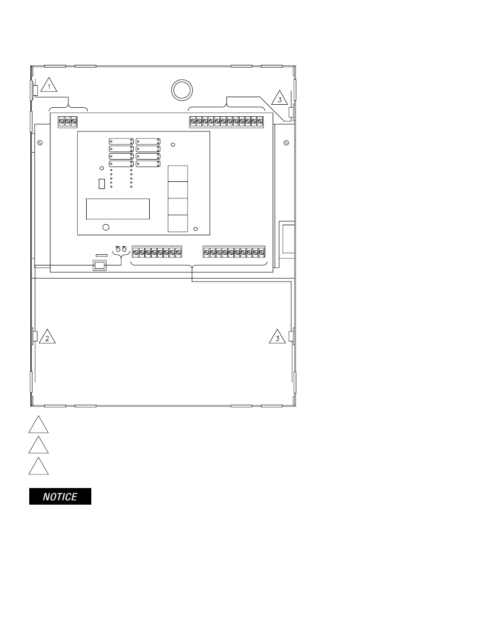
1
Power inputs
2
Battery leads
3
Using the cable clamps provided, route all other wiring away from power input wiring.
Wire Routing for PFC-4410RC
(*Shown with false front removed)
All field installed wiring connected to this panel must maintain a spacing of 1/4" between all electric light, power, class 1 or non-
power limited fire protective signaling conductors.
ZONE 1
ZONE 2
ZONE 3
ZONE 4
OUTPUT 1
OUTPUT 2
OUTPUT 3
OUTPUT 4
PROGRAM
MODE
RUN
MODE
AC POWER
POWER TBL
SYSTEM TBL
SUP TBL
GROUND
FAULT
SUP 1/ABORT
SUPERVISORY 2
COMMON ALARM
ALARM SILENCE
STEADY: DISCHARGING
FLASHING: PRE-
DISCHARGE
RUN
PROGRAM
SET
SELECT
FUNCTION
SCROLL-DOWN
BUZZER SILENCE
SIGNAL SILENCE
SYSTEM RESET
SCROLL-UP
BUZZER SILENCE
VIEWING ANGLE
RED OUTPUT LED STEADY: ABORT
DWG# 3550-16
}
LAMP TEST