Lamp test, Remote annunciator model ra-4410rc operation, Test procedure – Potter PFC-4410RC User Manual
Page 16: Test procedure (canada)
16
PFC-4410RC • 5403550 • REV Q • 11/12
Lamp Test
When the panel is in a Normal Condition, pushing the two top buttons will illuminate all of the LED's and display for
approximately one second.
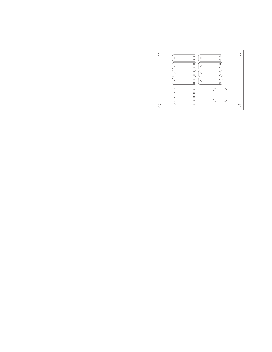
Remote Annunciator Model RA-4410RC Operation
Red LED’s:
Initiating Device Circuits Active (4)
Notification/Release Circuits Active (4)
Common Alarm (1)
Green LED’s: AC Power
Yellow LED’s: Initiating Device Circuits troubles (4)
Output Circuit Troubles (4)
Supervisory Initiating Zone (4)
Supervisory Bell Output Active (4)
(1) each: Sup 1/Abort, Supervisory 2, Power Trouble,
Supervisory Trouble, System Trouble, Ground Fault,
Pre-Discharge/Discharging, Alarm Silenced
The appropriate LED flashes to indicate a change of status on the panel. A trouble or supervisory condition will flash the appropriate
Yellow LED indicating the location of the condition. If any outputs are programmed as TROUBLE or SUPERVISORY BELL, that
Yellow output LED will flash indicating the output is activated. Pressing the BUZZER SILENCE button on the panel changes the
flashing zone Amber LED to steady on and turns the flashing Yellow output LED off.
An alarm condition will flash a Red LED indicating the zone in alarm and any outputs mapped to that zone that have activated.
Pressing the SIGNAL SILENCE button changes the flashing Red Zone LED to steady on and the flashing Red Output LED mapped
to that zone off unless the output is programmed as RELEASE. In addition, the Yellow ALARM/ SILENCE LED will light.
Any zone programmed as WATERFLOW is considered non-silenceable so the signal and buzzer silence buttons will have no
effect on the flashing zone and output LED's. A buzzer on the annunciator sounds for any trouble condition. When the panel
has a trouble or supervisory condition, pressing the SILENCE/LAMP TEST button silences the condition at the panel and all
annunciators. When no non-silenced trouble or supervisory conditions exist, pressing the SILENCE/LAMP TEST button can be
used to test the LED's.
The release panel supervises and communicates with the annunciator via separate connections for the RS-485 communication and
24VDC power requirements of the RA-4410RC. Separate cables should be used for power and communication. Shielded cable
shall be used for the communication line. Up to four annunciators can be connected to one panel. A rotary switch is provided on
the panel to indicate how many annunciators are connected. Another rotary switch is on the annunciator to set the address. The
annunciators must be addressed consecutively. See page 89 for wiring information. Refer to bulletin #8840024 for installation
instructions and maximum wire run.
Test Procedure
The system should be inspected, tested and maintained in accordance with NFPA-72 National Fire Alarm Code, Chapter 10 and
any other requirements of the local authority having jurisdiction.
Test Procedure (Canada)
The system should be inspected, tested and maintained in accordance with ULC Standard CAN/ULC-S536 and any other
requirements of the local authority having jurisdiction.
Testing should be done as a minimum as described below
1. Notify the fire department or other receiving station if alarm, supervisory and/or trouble signals are transmitted.
2. Notify the proper building personnel so that audible and/or visual signals can be ignored.
3. If the release panel is monitored by a building fire alarm panel, take appropriate action to eliminate any unwanted events.
4. Momentarily open each of the following circuits.
Each initiating device zone
•
Supervisory circuit
•
Notification Appliance/Releasing circuit - observe that this results in a trouble condition and all indicators operate as
•
described in the appropriate preceding section for the particular circuit that is faulted.
RED OUTPUT LED STEADY: ABORT
ZONE 1
ZONE 2
ZONE 3
ZONE 4
OUTPUT 1
OUTPUT 2
OUTPUT 3
OUTPUT 4
AC POWER
POWER TBL
SYSTEM TBL
SUP TBL
GROUND FAULT
SUP 1/ABORT
SUPERVISORY 2
COMMON ALARM
ALARM SILENCE
STEADY: DISCHARGING
FLASHING: PRE-DISCHARGE
LAMP TEST
SILENCE
DWG# 3550-17