Potter PFC-4410RC User Manual
Page 70
70
PFC-4410RC • 5403550 • REV Q • 11/12
OBSERVE POLARITY
WHEN CONNECTING
SMOKE DETECTORS
5.1K
VALVE
TAMPER
OSYSU
PCVS
5.1K
EOLR
5.1K
EOLR
5.1K
EOLR
5.1K
EOLR
5.1K
EOLR
AUX.
POWER
24VR DC
SUP 1/
ABORT
SUPV 2 ZONE 1
HEAT OR
SMOKE
DETECTORS
ZONE 2
HEAT OR
SMOKE
DETECTORS
ZONE 3
HEAT OR
SMOKE
DETECTORS
ZONE 4
MANUAL
RELEASE
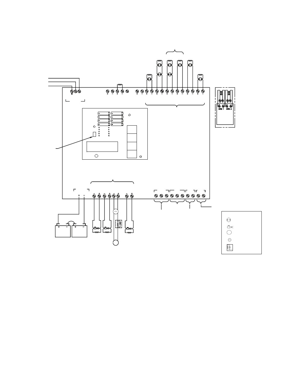
PANEL INPUTS (INITIATING ZONES)
CONNECT TO NORMALLY OPEN DEVICES
OR COMPATIBLE 2 WIRE SMOKE
DETECTORS.
MAXIMUM LINE RESISTANCE: 100 OHMS
(EXCEPT WITH LINEAR HEAT DETECTION)
OPTIONAL CA2Z MOUNTING LOCATION
EACH CA2Z WILL CONVERT
2 CLASS B ZONES INTO 2
CLASS A ZONES
OPTIONAL CLASS A
CONNECTIONS EOLR IS
NOT USED FOR CLASS A
OPTIONAL
CA2Z CLASS A
MODULE
DWG #3550-28
NO
COM
NC
NC
NO
NO
NO
COM
COM
COM
TROUBLE
SUPV
ALARM
SUPERVISORY
LOW AIR
VALVE TAMPER
WTRFL
ALARM CONDITION
SMOKE DET.
HEAT DET.
PULL STATION
WATERFLOW
WATERFLOW
TROUBLE CONDITION
PANEL PROBLEM
LOSS OF AC
LOSS OF BATTERY
WIRING PROBLEM
RELAY CONTACTS
DRY CONTACTS RATED AT 3A, 30VDC RESISTIVE
5.1K
EOLR
5.1K
EOLR
12V BATT.
12V BATT.
POS
NEG
POS
NEG
RE
D
RE
D
RE
D
5.1K
EOLR
RE
D
BLAC
K
BLAC
K
BLAC
K
BLAC
K
BATTERY CABLE
OBSERVE POLARITY
RED +
BLACK -
BATT
PANEL OUTPUTS (INDICATING CIRCUITS)
NON-POWER
LIMITED AND
SUPERVISED
SUPERVISORY
BELL
OUTPUT
4
eAEROSOL
CIRCUIT
OUTPUT
3
GENERAL
ALARM
BELL
OUTPUT
2
GENERAL
ALARM
BELL
OUTPUT
1
PROGRAM
SWITCH
NON-POWER
LIMITED AND
SUPERVISED
AC IN
CONNECTOR
EARTH GROUND - GREEN
NEUTRAL - WHITE
HOT - BLACK
TO CIRCUTI BREAKER PANEL
120VAC/60Hz
165 VA MAX.
220VAC/50Hz
185 VA MAX.
24VNR DC RS-485
S
120 OHM
ZONE 1
ZONE 2
ZONE 3
ZONE 4
OUTPUT 1
OUTPUT 2
OUTPUT 3
OUTPUT 4
PROGRAM
MODE
RUN
MODE
AC POWER
POWER TBL
SYSTEM TBL
SUP TBL
GROUND
FAULT
SUP 1/ABORT
SUPERVISORY 2
COMMON ALARM
ALARM SILENCE
STEADY: DISCHARGING
FLASHING: PRE-
DISCHARGE
RUN
PROGRAM
SET
SELECT
FUNCTION
SCROLL-DOWN
BUZZER SILENCE
SIGNAL SILENCE
SYSTEM RESET
SCROLL-UP
BUZZER SILENCE
VIEWING ANGLE
RED OUTPUT LED STEADY: ABORT
N 120
Observe polarity when connecting. The EOL Diode Assembly
eMatch Protection Assembly is non-polarized.
EOL
DIODE
ASSY
RE
D
BLAC
K
eA
z
YELLO
W
GREE
N
See page 89 or label inside panel door for smoke detector
compatibility data.
See page 85 for battery information.
Wiring Diagram Program #28
Single Hazard, 2 Detection Zones mapped to 1 eAEROSOL Circuit, 1 Supervisory Zone,
1 Manual Station Zone, and 1 Abort Circuit
}
LAMP TEST
10. Refer to pgs. 16, 83-85 for installation, test and
maintenance information.
11. Maximum resistance on outputs is 10 ohms. Maximum
resistance on outputs programmed as releasing, is 1
divided by current requirements of solenoid.
12. Notification outputs do not provide synchronization.
If synchronization is needed, refer to the NAC table on
page 90. Synchronization is only on one circuit and not
betweeen circuits. The maximum cannot exceed 1 amp or
whatever the maximum that the sync' module can support,
whichever is lower.
NOTES:
1. Connect only UL Listed 24VDC devices to indicating
circuits.
2. Connect EOL Diode assembly IN SERIES with aerosol on
eAEROSOL circuit.
3. Connect eMatch Protection IN PARALLEL with aerosol
on eAEROSOL circuit.
4. Leave EOLR (provided) on all unused circuits.
5. Polarity is shown on indicating circuits in an activated
(off-normal) condition.
6. Polarity reverses when output is activated.
7. Maximum current per output is 1 Amp. Maximum voltage
is 33VDC.
8. Outputs identified as Release are Special Application. All
other outputs are Regulated 24 VDC, Rated 1 Amp each,
2.5 Amp total for all 4 circuits.
9. All initiating and NAC/Release circuits are supervised and
power limited. See note 3 on page 92 for power limited
wire routing instructions. All frequencies are continuous.
Initiating device
Notification appliance
eAEROSOL
eMatch Protection assy.
End-of-Line diode assy.
Legend
eA
z