2 description of the control module – EVCO EVCLC33DJ2 User Manual
Page 18
EVCO S.p.A.
Vcolor 338 L | Installer manual ver. 2.0 | Code 144VC338LE204
page 18 of 66
4.2
Description of the control module
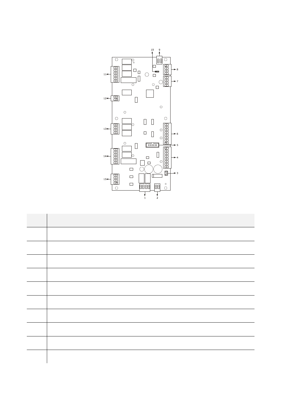
The following drawing illustrates the layout of the device's control module.
The following table illustrates the meaning of the device control module parts.
PART
MEANING
1
digital outputs K1 and K2
2
power supply
3
external buzzer output
4
digital inputs for clean contact
5
reserved
6
analogue inputs
7
reserved
8
user interface communication port
9
analogue output
10
dip switch to activate the terminal resistor
This manual is related to the following products:
See also other documents in the category EVCO Hardware:
- EV3B22N7 (2 pages)
- EV3B23N7 (2 pages)
- EV3B31N7 (2 pages)
- EV3X21N7 (2 pages)
- EVK203N7 (2 pages)
- EVK204N9 (5 pages)
- EVK214N9 (6 pages)
- EVX201N7 (8 pages)
- EVX225N7 (6 pages)
- EVXS214N9 (8 pages)
- EVXV201N7 (9 pages)
- EVR202N7 (10 pages)
- EVRS204N9 (8 pages)
- EVRS225N9 (10 pages)
- TM102A (2 pages)
- EVK404N9 (8 pages)
- EPD4BF3 (2 pages)
- EPD4BF3 (70 pages)
- EV6223P7 (2 pages)
- EVB1226N9XXC (92 pages)
- EVB1214N9 (88 pages)
- EVRSF204N9VRB (8 pages)
- EVF204N9 (8 pages)
- EVF205N9 (8 pages)
- EVF214N9 (8 pages)
- EVF215N9 (8 pages)
- EK820AP7 (4 pages)
- EK825AP7 (14 pages)
- EVCSR818P9EF (94 pages)
- EVF815P9 (2 pages)
- EVF815P9 (60 pages)
- EVF818P9 (2 pages)
- EVF818P9 (76 pages)
- EVX802P7 Installer manual (2 pages)
- EVX802P7 Installer manual (66 pages)
- EVXS815P9 Installer manual (2 pages)
- EVXS815P9 Installer manual (60 pages)
- EVXV802P7 Installer manual (2 pages)
- EVXV802P7 Installer manual (66 pages)
- EVK802P7 (2 pages)
- EVFTFT818P7U (2 pages)
- EVFTFT818P7U Installer manual (94 pages)
- EV7601J6 (2 pages)
- EV9303J9 (2 pages)
- EV9313J9 (2 pages)