EVCO EVCLC33DJ2 User Manual
Page 15
EVCO S.p.A.
Vcolor 338 L | Installer manual ver. 2.0 | Code 144VC338LE204
page 15 of 66
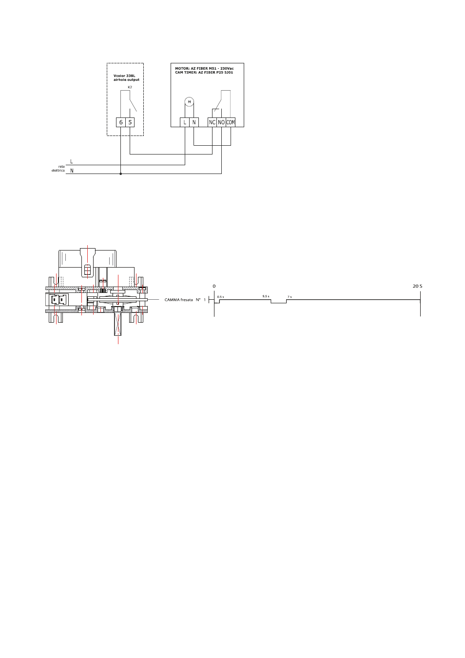
Example of connection for motorized air vent cam timer, such as FIBER Pxx series.
The following scheme is an example of parameters set up for the cam timer below
u2 = 140 (14 seconds) time-delay for cam rotation
u3 = 10 (1 second) motor activation time for limit switch rearm (short milling)
u4 = 30 (3 seconds) motor activation time for limit switch rearm (long milling)
3.2
Warnings for the electric connection
-
do not use electric or pneumatic screwdrivers on the device terminal board
-
if the device has been taken from a cold to hot place, humidity could condense inside; wait about 1 hour before powering it
-
make sure that the power supply voltage, the frequency and the device electric power, correspond to those of the local
power supply; see chapter 20 “TECHNICAL DATA”
-
disconnect the device power supply before proceeding with any type of maintenance
-
position the power cables as far away as possible from the signal cables
-
the terminating resistor must be connected in order to reduce the reflections on the signal transmitted along the cables that
connect the user interface to the control module.
-
for repairs and information regarding the device, contact the EVCO sales network.