Controls and indicators, Approximate operating range – Kenwood KRF-V8881 D User Manual
Page 17
Attention! The text in this document has been recognized automatically. To view the original document, you can use the "Original mode".
Controls and indicators
VR-SO3O/Vn-2O8D/KRF.V0881D/KRF-V7771D lEn/K]
The Remote Control unit provided with the Receiver can also control KENWOOD MD recorder, cassette decks, CD pJayer, DVD
player and LD player which are connected to it through system control cords. For details of the controllable functions, refer to
the instruction manuals of these components.
'
w
77
RC ; Infrared system
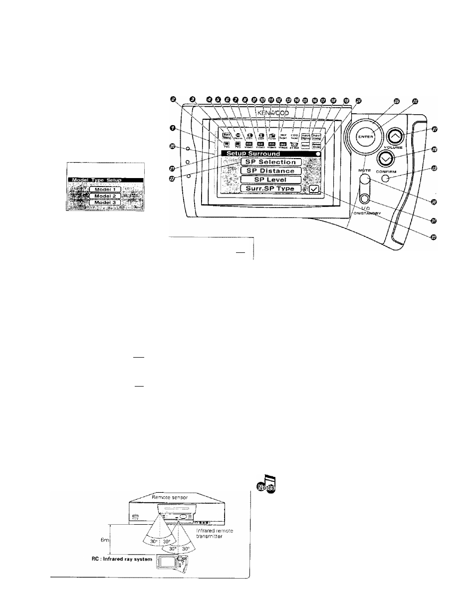
Perform "Model Type Setup"
of the RC before using it.
Thefollowing menu display ap
pears after the batteries are
loaded for the first time.
Segment screen
О Segment screen
The fixed icons are displayed in
this area
©TVl icon
Select to display the TVl control
screen
©Main
Menu
icon
-Qf!
Select to display the Main Menu
screen.
OTV2 icon
-QB
Select to display the ТУ2 control
screen.
©Phono icon
-ffi]
Select to select the PHONO in
put,
©Videol icon
-tjCi
Select to control Videol.
©GDI icon
-oa
Select TO control CD1.
©Video2 icon
-Qg
Select to control Video2.
©CD2 icon
~ЙВ
Select to control CD2.
[Room В only)
©Videos icon
“СШ
Select to control Videos.
©Tuner icon
-I'M
Select to control Tuner
©Video4icon
-Ijg
Select to control Video4
©MD/Tapel icon
-J3E
Select to control MD or Tapel,
©CD2/Tape2 icon -¡
4|]
Select to monitor the CD2/Tape2
input, (Room A only)
©AV AUX icon
-SB
Select to select the AV AUX In
put.
©Input Digitai icon -[g]
Select to play a digital input or to
Switch between Auto and Manual,
©Macro icon
Select TO control Macro.
©Input Analog icon -CS)
Select to play an analog input.
©Remote Mode icon -[^
Select so switch the remote con
trol operation mode without
changing the selected input.
The displayed icons are variable depending of the
'ModBl Type Setup"
for
matching specifications with the Raciaver which uses the RC unit and
"Setup"
for
matching specifications with connected source coinpoftent.
•n
rl'
. S'
,( ;
St. L
Menu screen
Operatiori keys
©Menu screen -PB
Control key icons and con
trol levels are displayed in
this area.
©Status display -[j£
The example in the illus
tration shows the "Setup
Surround" status.
©SP Selection icon
Select to set up the speak
ers.
©Return icon
Select to return to the pre
vious menu screen.
©Status display -Qg
Shows the com municstion
status.
©Joy stick key
-gB
This key ¡s used to select an
icon. This key can be controlled
in 4 directions.
©ENTER key
Press to enter the selection of
an icon.
©VOLUME (up) Control key
Press to increase the volume.
©VOLUME (down) control
key
Press to decrease the volurne.
©CONFIRM key
Press to select the currently
displayed items.
©MUTE key
Press to mute the audio
temporarily,
© I /(!) (ON/STANDBY) key
Press to turn this unit and the
components connected to it
through system cords between
ON and STANDBY modes.
Approximate operating range
t.The supplied batteries are intended for use in operation
check. Therefore, their lives may be shorter than ordinary
batteries,
2. When the remote-controllable distance gets shorter than
before, replace all four batteries with new ones.
3. Malfunction may occur if direct sunlight or the light of a high-
frequency lighting fluorescent lamp enters the remote sen
sor, in such a case, change the system instBlIation position to
prevent the malfunction,
4. The RC display may show erroneous information whan the
BC unit IS operated from outside the specified range.