Cub Cadet Z-Force S Series User Manual
Page 68
Z-Force-S
62
NOTE: The hydro arms and output bevel gears
have master splines to time them to each
other. See Figure 6.53.
10d. Install the snap ring.
10e. Repeat for the right output bevel gear assem-
bly.
10f. Slide the bevel gear assemblies onto the
speed cam assemblies.
11.
Place both output bevel gear assemblies on the
bench, facing each other. With both assemblies
resting on the same points of the speed cam, insert
both shafts into the coupler. See Figure 6.54.
12.
Drive the roll pins through the coupler and the shafts
to hold the assembly together.
NOTE: The top of the roll pins (as they sit in the
steering gearbox) must be flush with the
coupler or they will bind against the gearbox
cover.
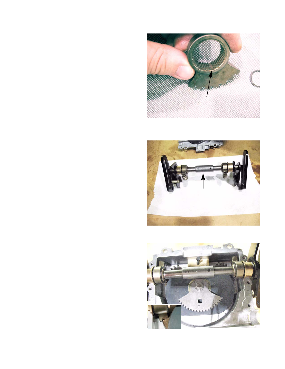
13.
Insert the speed cam assemblies in the lower hous-
ing.
•
Align the hole in the input sector gear with the
center of the square recess at the front of the
lower housing. See Figure 6.55.
NOTE: The wooden block from step 9 will hold the
cam in place.
•
The bevel gears should face away from the
input sector gear.
•
The first tooth of each output bevel gear should
rest in the first valley of the bevel gears in the
bottom of the lower housing. See Figure 6.55.
inset.
NOTE: If one or both of the output bevel gears are
out of time, the steering rack will lose travel
on the affected side
Figure 6.53
Master spline
Figure 6.54
Coupler
Both speed cam are in line
Figure 6.55