Electrical system, Caution – Cub Cadet Z-Force S Series User Manual
Page 109
Electrical System
103
5.
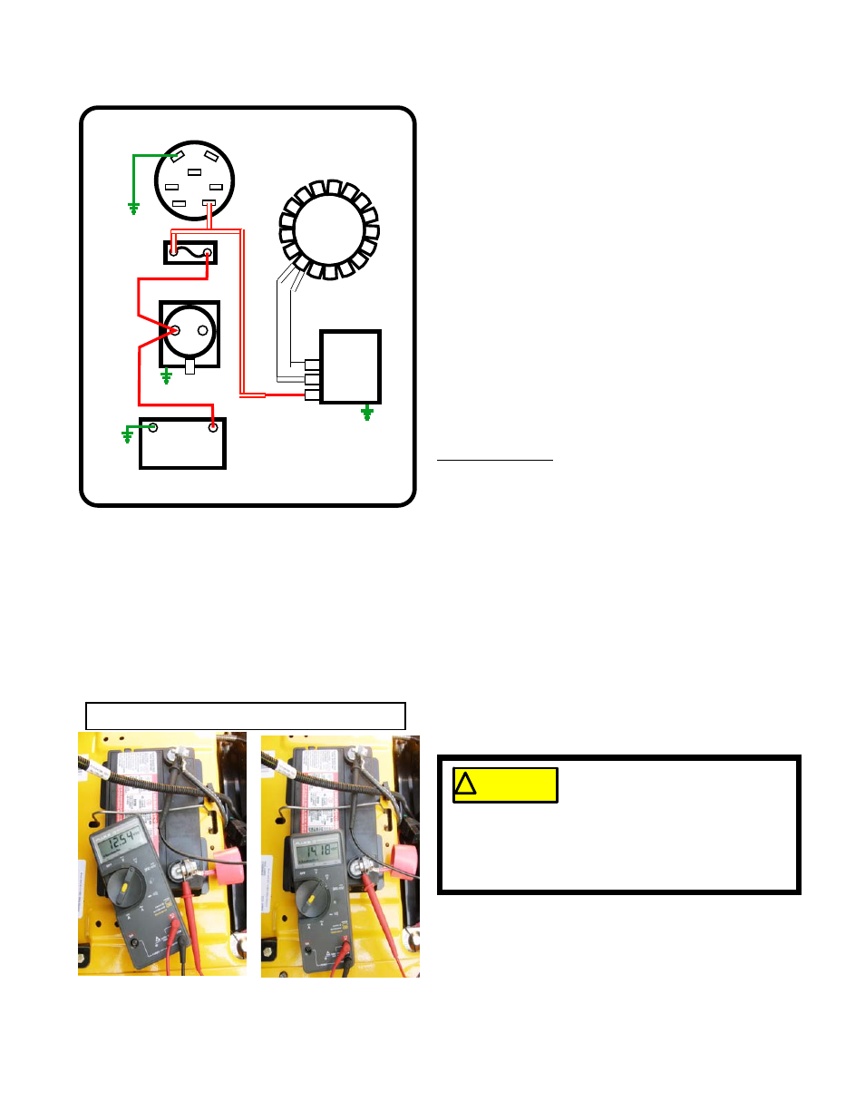
From the harness connector: See Figure 7.22.
5a.
The red/white trace wire leads to the 20A fuse.
5b.
From the fuse, the wire connects to the starter
solenoid, sharing the “hot” post with the battery
cable.
5c.
The shared post on the starter solenoid pro-
vides the final connection for the alternator out-
put to reach the battery.
Testing Sequence:
1. Charge and check the battery or confirm that a
known-good battery is installed in the mower.
2.
Make a visual inspection of the mower. Look for:
• Loose connections - power and ground
• Corroded connections - power and ground
• Ground wires all present
• Blown fuse
• Obvious damage to the wiring harness- burns,
chafed wires, kinks.
3.
Quick check, to see if there is a problem.
See Figure 7.23.
3a.
Check base-line battery voltage.
3b.
Start the engine and advance the throttle to
3,000 RPM.
3c.
Check operating voltage.
3d.
If operating voltage does not rise with engine
RPM, proceed with the system check.
*
$
/
6
$
0
%
.H\6ZLWFK
6WDUWHU6ROHQRLG
%DWWHU\
1(*
326
)XVH
*UQG
*URXQG
5HJXODWRU
5HFWLILHU
$
$
%
$OWHUQDWRU
6WDWRU
*URXQG
*URXQG
Figure 7.22
Stopped -12.54v Running 14.18v
Figure 7.23
This step involves running the
engine. Before starting the engine,
make sure that no unsafe conditions
will arise from doing so. Potential hazards include:
motion hazards from contact with spinning parts or
moving equipment, heat-source hazards, and
asphyxiation hazard.
! CAUTION
! CAUTION