Cub Cadet Z-Force S Series User Manual
Page 67
Steering
61
7.
Apply a dab of 737-0300A Durina
TM
grease to the
side of the steering shaft.
8.
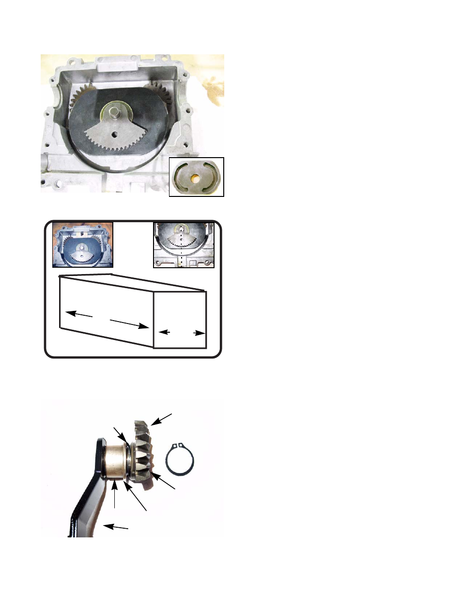
Install the internal cam so that the rollers on the
bevel gears fit inside the groves on the underside of
the cam. See Figure 6.50.
9.
Center the cam so that the hole in the sector gear
lines up with the center of the void where the wear
block goes. See Figure 6.51. right inset.
NOTE: A wooden block can be used to hold the cam in
place while timing the internal components. The
measurements of the block should be 27/32” wide
x 1.5” long. The height should be at least a 1/2”.
See Figure 6.51.
NOTE: Putting a screw in the top of the block makes it
easier to remove and prevents closing the box with
the block still inside. See Figure 6.51. left inset.
10. Re-assemble the output bevel gear assemblies.
10a. Place a bushing over the hydro arm with the
flange facing away from the arm.
See Figure 6.52.
10b. Place the wave washer over the hydro arm.
See Figure 6.52.
10c. Place the output bevel gear on the hydro arm
with the chamfer facing away from the hydro
arm. See Figure 6.52.
NOTE: If the output bevel gears are put on backwards it
will throw off the timing of the gearbox.
Figure 6.50
Figure 6.51
27/32”
1.5”
Figure 6.52
Hydro arm
Bushing
Wave washer
Output bevel gear
Chamfer
Bushing flange