Pto circuit, Electrical system – Cub Cadet Z-Force S Series User Manual
Page 113
Electrical System
107
PTO Circuit
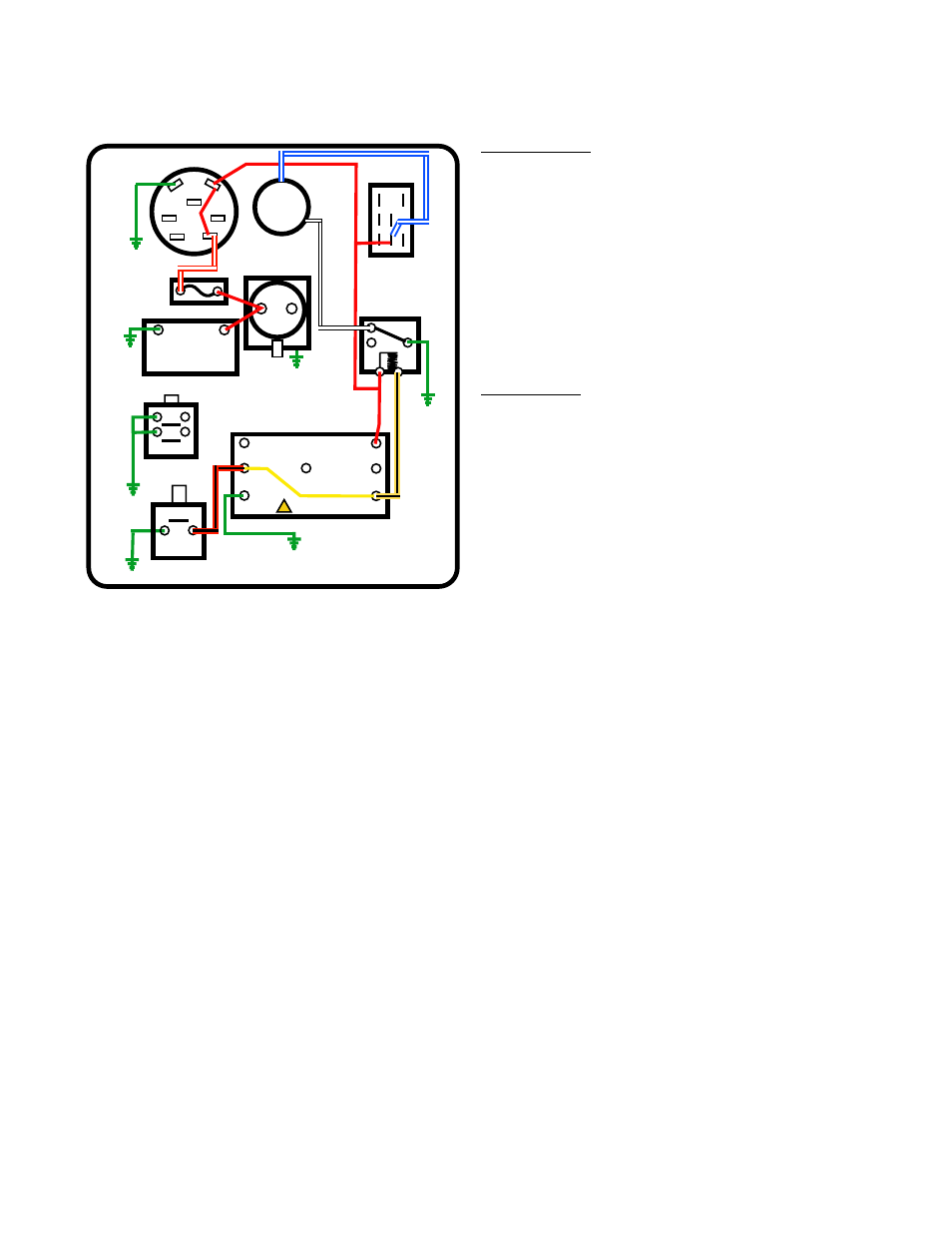
Basic Operation: See Figure 7.29.
1. With the key switch in any position other than OFF,
the A1 terminal supplies power to the windings of the
PTO relay and to the C-COM terminal of the PTO
switch.
2.
The PTO clutch gets power from the A1 terminal of
the key switch through the C-N.O. terminal of the
PTO switch when it is turned ON.
3.
The PTO clutch gets ground through the PTO relay
COM terminal via the PTO relay N.C. terminal when
the relay is not energized.
Safety Circuits:
There are some conditions when it is best to automati-
cally turn off the mower deck to ensure safety.
• When the mower is put in Reverse, we want to turn
off the blades unless the RevTec (RMC) module
has been armed and engaged.
• When the operator leaves the seat for any reason,
we want to turn off the blades.
NOTE: When the operator leaves the seat without setting
the park brake, the engine turns off stopping the
blades as well.
1.
The PTO clutch loses its ground when the PTO relay is energized. See Figure 7.29.
1a.
The Yellow/black trace wire connected to the windings of the PTO relay leads to the “E-PTO” terminal on
the RMC module.
1b.
The reverse switch has N.O. (Normally Open) contacts.
• A green wire from one terminal is a ground path.
• A red/black trace wire on the second terminal leads to the “Rev.Sw” terminal on the RMC module.
1c.
When the mower is put in reverse, the plunger on the switch is depressed, closing the contacts.
1d.
The closed contacts complete a ground path that passes through the RMC module from the Rev.Sw ter-
minal to the E-PTO terminal when the RMC module is not armed and activated.
NOTE: When the RMC module is armed and activated, Rev.Sw terminal is disconnected from the E-PTO ter-
minal inside the module.
1e.
The ground path reaches the PTO relay windings, and the PTO relay is energized when the mower is put
in reverse.
50&0RGXOH
6HDW6Z
56:
*UQG
$SZU
$SZU
(372
³2Q´
*
$
/
6
$
0
%
.H\6ZLWFK³5XQ´
6WDUWHU6ROHQRLG
%DWWHU\
1(*
326
)XVH
372
&OXWFK
3726ZLWFK2Q
$
%
&
&20
12
1&
3725HOD\
$W5HVW
1&
1&
6HDW6ZLWFK
'HSUHVVHG
*URXQG
*UQG
*URXQG
*URXQG
*URXQG
*URXQG
*URXQG
12
5HYHUVH6ZLWFK
$W5HVW
Figure 7.29