Front and rear deck lift shaft assembly – Cub Cadet Z-Force S Series User Manual
Page 157
Decks and Lift Shaft
151
Front and rear deck lift shaft assembly
The Z-force-S has two deck lift shafts. The same proce-
dure is used to remove either one.
To remove/replace a lift shaft:
1. Remove the deck by following the steps described at
the beginning of this chapter.
2.
Remove the left control panel by following the steps
described in Chapter 4: Body/Chassis.
NOTE: On units equipped with a 60” deck, the right control
panel will need to be removed as well.
3.
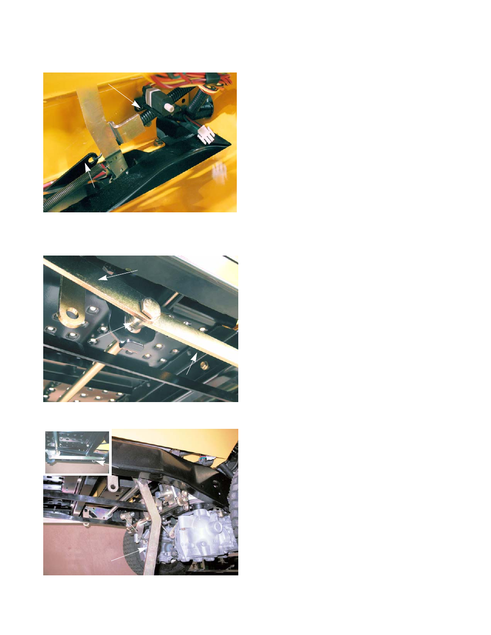
Remove the deck lift assist spring(s).
See Figure 8.28.
NOTE: 48” decks use a single deck lift assist spring on the
left hand side. 60” decks have a lift assist spring on
both sides.
4.
Remove the shoulder bolt that connects the pedal
link to the front lift shaft and middle link using a 15/
16” wrench and a 9/16” wrench. See Figure 8.29.
NOTE: There is a spacer between the middle link and the
lift shaft.
5.
Remove both middle links using a 15/16” wrench and
a 9/16” wrench. See Figure 8.30.
NOTE: The middle link on the left side is angled. The mid-
dle link on the right is straight.
Figure 8.28
Lift assist spring
Front lift shaft
Figure 8.29
Pedal link
Middle link
Spacer
Figure 8.30
Left middle link
Right middle link