1 sparing redundancy state sensor – next steps, 5 ecc and address parity, 1 memory correctable and uncorrectable ecc error – Kontron S4600 SEL Troubleshooting User Manual
Page 86: Sparing redundancy state sensor, Next steps, Ecc and address parity, Memory correctable and uncorrectable ecc error
Memory Subsystem
System Event Log Troubleshooting Guide for EPSD
Platforms Based on Intel
®
Xeon
®
Processor E5 4600/2600/2400/1600/1400 Product Families
76
Intel order number G90620-002
Revision 1.1
7.4.1
Sparing Redundancy State Sensor – Next Steps
This event is accompanied by memory errors indicating the source of the issue. Troubleshoot accordingly (probably replace affected
DIMM).
For boards with DIMM Fault LEDs, the appropriate Fault LED is lit to indicate which DIMM was the source of the error triggering the
Mirroring Failover action, that is, the failing DIMM.
7.5 ECC and Address Parity
1. Memory data errors are logged as correctable or uncorrectable.
2. Uncorrectable errors are fatal.
3. Memory addresses are protected with parity bits and a parity error is logged. This is a fatal error.
7.5.1
Memory Correctable and Uncorrectable ECC Error
ECC errors are divided into Uncorrectable ECC Errors and Correctable ECC Errors. A “Correctable ECC Error” actually represents a
threshold overflow. More Correctable Errors are detected at the memory controller level for a given DIMM within a given timeframe.
In both cases, the error can be narrowed down to particular DIMM(s). The BIOS SMI error handler uses this information to log the
data to the BMC SEL and identify the failing DIMM module.
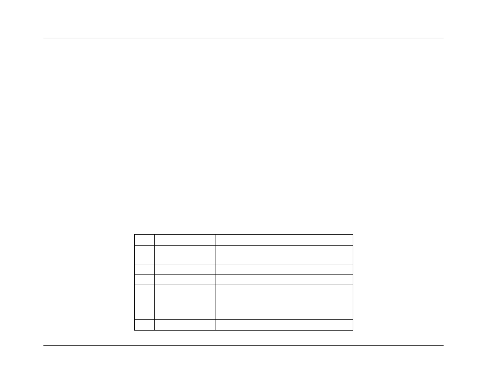
Table 63: Correctable and Uncorrectable ECC Error Sensor Typical Characteristics
Byte
Field
Description
8
9
Generator ID
0033h = BIOS SMI Handler
11
Sensor Type
0ch = Memory
12
Sensor Number
02h
13
Event Direction and
Event Type
[7] Event direction
0b = Assertion Event
1b = Deassertion Event
[6:0] Event Type = 6Fh (Sensor Specific)
14
Event Data 1
[7:6]
– 10b = OEM code in Event Data 2