1 mirroring redundancy state sensor – next steps, 4 sparing redundancy state, Mirroring redundancy state sensor – Kontron S4600 SEL Troubleshooting User Manual
Page 84: Next steps, Sparing redundancy state
Memory Subsystem
System Event Log Troubleshooting Guide for EPSD
Platforms Based on Intel
®
Xeon
®
Processor E5 4600/2600/2400/1600/1400 Product Families
74
Intel order number G90620-002
Revision 1.1
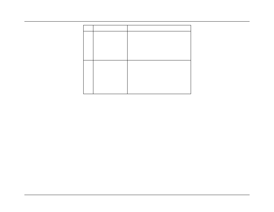
Byte
Field
Description
15
Event Data 2
Location
[7:4] = Mirroring Domain
0-1 = Channel Pair for Socket
[3:2] = Reserved
[1:0] = Rank on DIMM
0-3 = Rank Number
16
Event Data 3
Location
[7:5] = Socket ID
0-3 = CPU1-4
[4:3] = Channel
0-3 = Channel A-D for Socket
[2:0] = DIMM
0-2 = DIMM 1-3 on Channel
7.3.1
Mirroring Redundancy State Sensor – Next Steps
This event is accompanied by memory errors indicating the source of the issue. Troubleshoot accordingly (probably replace affected
DIMM).
For boards with DIMM Fault LEDs, the appropriate Fault LED is lit to indicate which DIMM was the source of the error triggering the
Mirroring Failover action, that is, the failing DIMM.
7.4 Sparing Redundancy State
Rank Sparing Mode is a Memory RAS configuration option that
reserves one memory rank per channel as a “spare rank”. If any rank
on a given channel experiences enough Correctable ECC Errors to cross the Correctable Error Threshold, the data in that rank is
copied to the spare rank, and then the spare rank is mapped into the memory array to replace the failing rank.
Rank Sparing Mode protects memory data by reserving a “Spare Rank” on each channel that has memory installed on it. If a
Correctable Error Threshold event occurs, the data from the failing rank is copied to the Spare Rank on the same channel, and the
failing DIMM is disabled. Because the Sparing Domain is no longer redundant, a Sparing Redundancy State SEL Event is logged.