Elecraft XV Assembly Manual for XV222 User Manual
Page 7
- 4 -
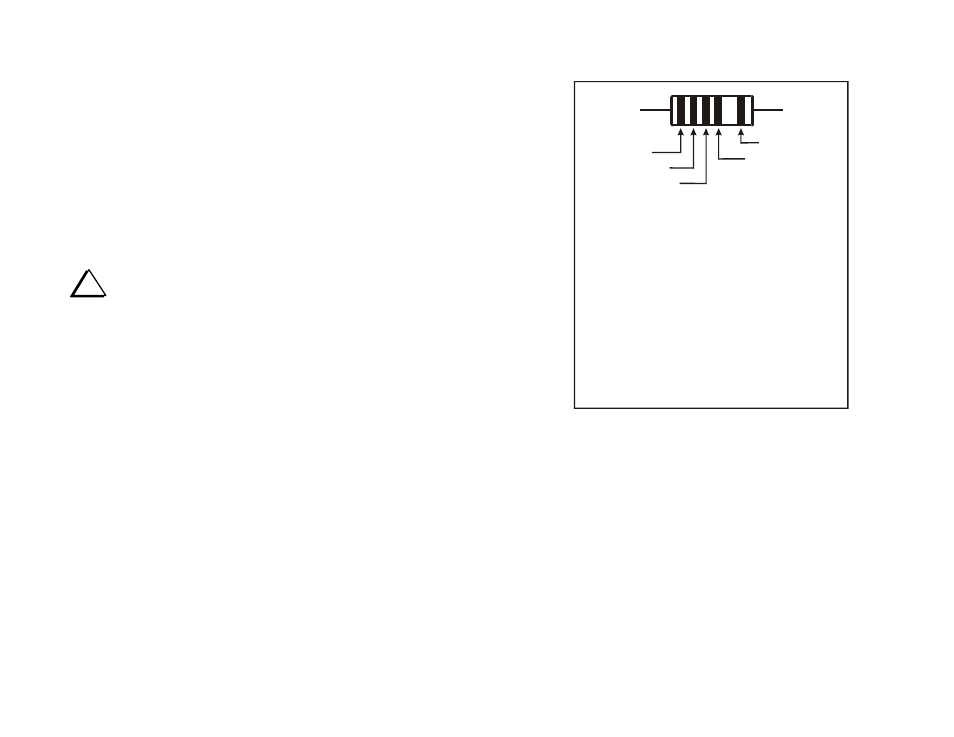
Reading Resistor Color Codes
It is very helpful if you learn to read the color codes. A color-code chart
showing how to read the four-color bands on resistors with a 5% or 10%
tolerance is shown in Figure 3. 1% resistors are similar except that they
use a fifth band to provide a way of showing another significant digit. For
example, a 1,500 ohm (1.5 k-ohm) 5% resistor has the color bands brown,
green and red signifying one, five and two zeros. A 1,500 ohm (1.5 k-ohm)
1% tolerance resistor has the color bands brown, green, black and brown
signifying one, five, zero, and one zero.
The optional band shown in Figure 3 indicates other performance
specifications for the resistor. When used, it is separated from the other
color bands by a wider space.
i
If in doubt of a resistor’s value, use a DMM. It may be difficult
to see the colors on some resistors, particularly 1% tolerance resistors with
a dark blue body. Do not be concerned with minor deviations of your
DMM reading from the expected value. Typical errors in most DMMs and
the tolerances of the resistors normally produce readings that are slightly
different from the value indicated by the color bands
.
Identifying Molded Inductors
Small molded inductors have color bands that use the same numeric values
as resistors but they start near the center of the inductor and work toward
the end. These colors are listed in the text after the value of the inductor,
for example: 27
H (red-vio-blk). The red stripe would be near the center
of the inductor and the black stripe would be closer to the end. On very
small chokes, the first color will be only slightly farther from one end than
the last color. There may be a variety of other stripes on inductors as well,
indicating their tolerance, conformance to certain specifications and other
data.
FIRST DIGIT
TOLERANCE:
OPTIONAL
SECOND DIGIT
MULTIPLIER
Black
Brown
Red
Orange
Yellow
Green
Blue
Violet
Gray
White
Silver
Gold
0
1
2
3
4
5
6
7
8
9
-
-
X 1
X 10
X 100
X 10K
X 10K
X 100K
X 1M
-
-
-
X 0.01
X 0.1
COLOR
DIGIT
MULTIPLIER
GOLD = 5%
SILVER = 10%
Figure 3. Resistor Color Code.
Identifying Capacitors
Capacitors are identified by their value and the spacing of their leads.
Small-value fixed capacitors usually are marked with one, two or three
digits and no decimal point. The significant digits are shown in parenthesis
in the text. For example: “C2, .01 (103)”.
If one or two digits are used, that is always the value in picofarads (pF). If
there are three digits, the third digit is the multiplier. For example, a
capacitor marked “151” would be 150 pF (15 multiplied by 10
1
).
Similarly, “330” is 33 pF and “102” is 1000 pF (or .001
F). You may
think of the multiplier value as the number of zeros you need to add on to
the end of the value.