Elecraft XV Assembly Manual for XV222 User Manual
Page 51
- 48 -
Lay the bottom cover on a clean, smooth surface with the heat spreader
facing up.
Remove the nuts from the long screws but do not remove the screws. If
you have installed feet on the bottom cover, place a small book that fits
between the feet under the cover so the long screws do not fall out.
Place the smaller thermal conduction pad over the screws. Orient the pad
so it does not hang over the edge of the heat spreader.
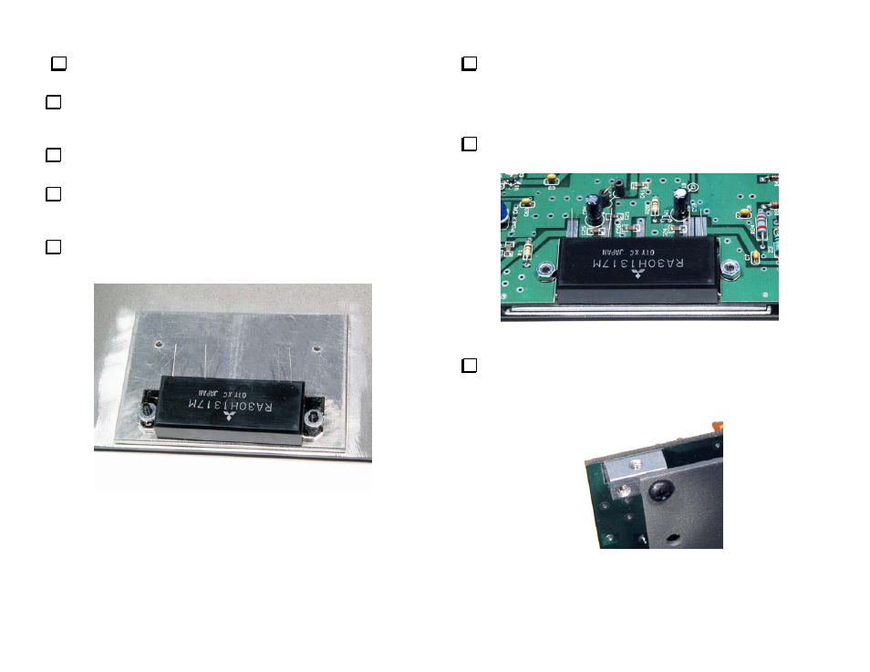
Position the RF power module on the two screws as shown in Figure 35.
Be sure the thermal conduction pad on the heat spreader is resting directly
against the bottom of the RF power module.
Place a flat washer on each screw as shown in Figure 35.
Figure 35. RF Power Module and Flat Washers in Place on the Heat
Spreader.
Slide the PCB under the leads on the RF power module and over the
screws until they pass through the holes in the PCB (see Figure 36). You
can rock the RF Power Module slightly on the screws and bend the leads
up as needed to slip the PCB under them and over the tops of the
mounting screws.
Place an internal tooth lock washer and nut on each screw and
tighten them finger tight.
Figure 36. RF PCB attached to the RF Power Module Screws.
Pick up the entire assembly and secure the four 2-D fasteners to the
bottom cover. Each corner is attached with one 3/16” (4.8 mm) black
screw (see Figure 37). The other two screw holes in each 2-D fastener
will secure the front, rear and side covers in later steps.
Figure 37. Bottom Cover Attached to 2-D Fastener.