Preparing for assembly – Elecraft XV Assembly Manual for XV222 User Manual
Page 5
- 2 -
Preparing for Assembly
Overview of the Kit
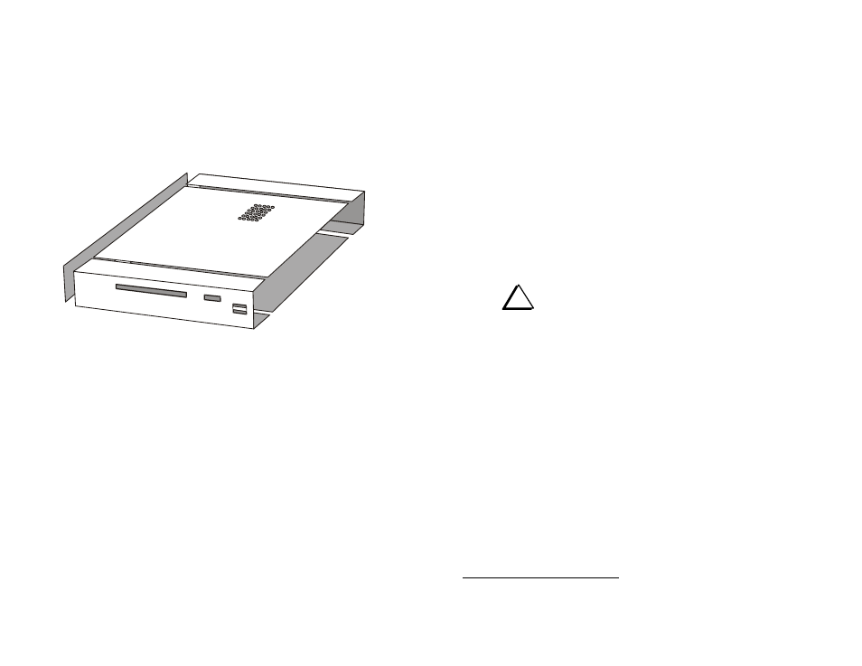
The Elecraft XV transverters use modular construction, both physically
and electrically. This concept extends to the chassis (Figure 1). Any
chassis element can be removed to provide access.
Figure 1. XV Transverter Modular Cabinet Parts.
There are two printed circuit boards (PCBs) in the transverter: the front
panel PCB, which sits vertically behind the front panel, and the large RF
PCB visible in the cover photograph.
The PCBs are interconnected using board-to-board connectors which
eliminates the need for a wiring harness. Gold-plated contacts are used on
these connectors for reliability.
Tools Required
You will need the following tools to build this kit
1
:
Fine-tip temperature-controlled soldering station with 700 or
800
F tip (370-430C). Do not use a high-wattage iron or gun
since this can damage pads, traces, or the parts themselves.
IC grade, small-diameter (.031”) solder (Kester #44 or equivalent).
Desoldering tools and supplies are invaluable if you make any
modifications or need to do any repairs. Narrow solder wick or a
good vacuum desoldering tool such as the Soldapullt® model
DS017LS are recommended. See Soldering, Desoldering and
Plated-Through Holes, on page 6 for more information.
i
DO NOT use acid-core solder, water-soluble flux
solder, additional flux or solvents of any kind. Use of any of
these will void your warranty.
Screwdrivers: a small, #2 Phillips and a small flat-blade for slotted
screws.
Needle-nose pliers.
Small-point diagonal cutters, preferably flush-cutting.
Digital Multimeter (DMM) for voltage checks and confirming
resistor values. A DMM with capacitance measurement capability
is desirable, but not required.
Noise generator (Elecraft N-Gen or equivalent) or signal generator
with output in the RF frequency range of the transverter.
RF power meter capable of measuring RF power levels up to 25
watts at the frequency used by the transverter.
50-ohm dummy load capable of handling 25 watts, minimum.
1
Refer to www.elecraft.com for tool sources and solder recommendations.
BACK PANEL
LEFT
SIDE PANEL
TOP
COVER
FRONT
PANEL
BOTTOM
COVER
(RIGHT SIDE
PANEL NOT
SHOWN)